www.balluff.com 29english
13
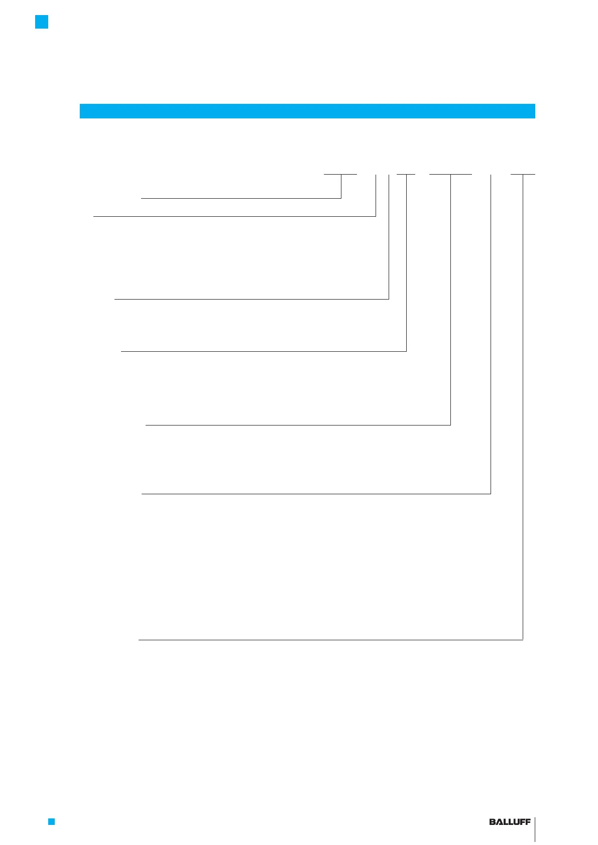
Ordering code
BTL7 - A 1 1 0 - M0500 - B - S32
Micropulse transducer
Interface:
A = Analog interface, voltage output 0 to 10 V
G = Analog interface, voltage output -10 to 10 V
C = Analog interface, current output 0 to 20 mA
E = Analog interface, current output 4 to 20 mA
Supply voltage:
1 = 20 to 28VDC
5 = 10 to 30VDC
Output gradient:
00 = Rising (e.g. C_00 = 0 to 20 mA)
10 = Rising + falling (e.g. A_10 = 10 to 0 V and 0 to 10 V)
70 = Falling (e.g. C_70 = 20 to 0 mA)
Nominal stroke (4-digit):
M0500 = Metric specification in mm, nominal length 500mm
(M0025 to M1016: A8, B8, Y8, Z8)
(M0025 to M7620: A, B, Y, Z)
Rod version, fastening:
A = Metric mounting thread M18x1.5, rod diameter 10.2mm
B = Metric mounting thread M18x1.5, O-ring, rod diameter 10.2mm
Y = 3/4"-16UNF thread, rod diameter 10.2mm
Z = 3/4"-16UNF thread, O-ring, rod diameter 10.2mm
A8 = Metric mounting thread M18x1.5, rod diameter 8mm
B8 = Metric mounting thread M18x1.5, O-ring, rod diameter 8mm
Y8 = 3/4"-16UNF thread, rod diameter 8mm
Z8 = 3/4"-16UNF thread, O-ring, rod diameter 8mm
Electrical connection:
S32 = 8-pin, M16 plug per IEC130-9
S115 = 8-pin, M12 plug
S135 = 6-pin, M16 plug per IEC130-9
S140 = 10-pin, plug
KA05 = Cable, 5m (PUR)
FA05 = Cable, 5m (PTFE)
BTL7-A/C/E/G_ _ _-M_ _ _ _-A/B/Y/Z(8)-S32/S115/S135/S140/KA_ _/FA_ _
Micropulse Transducer - Rod Style
 Loading...


