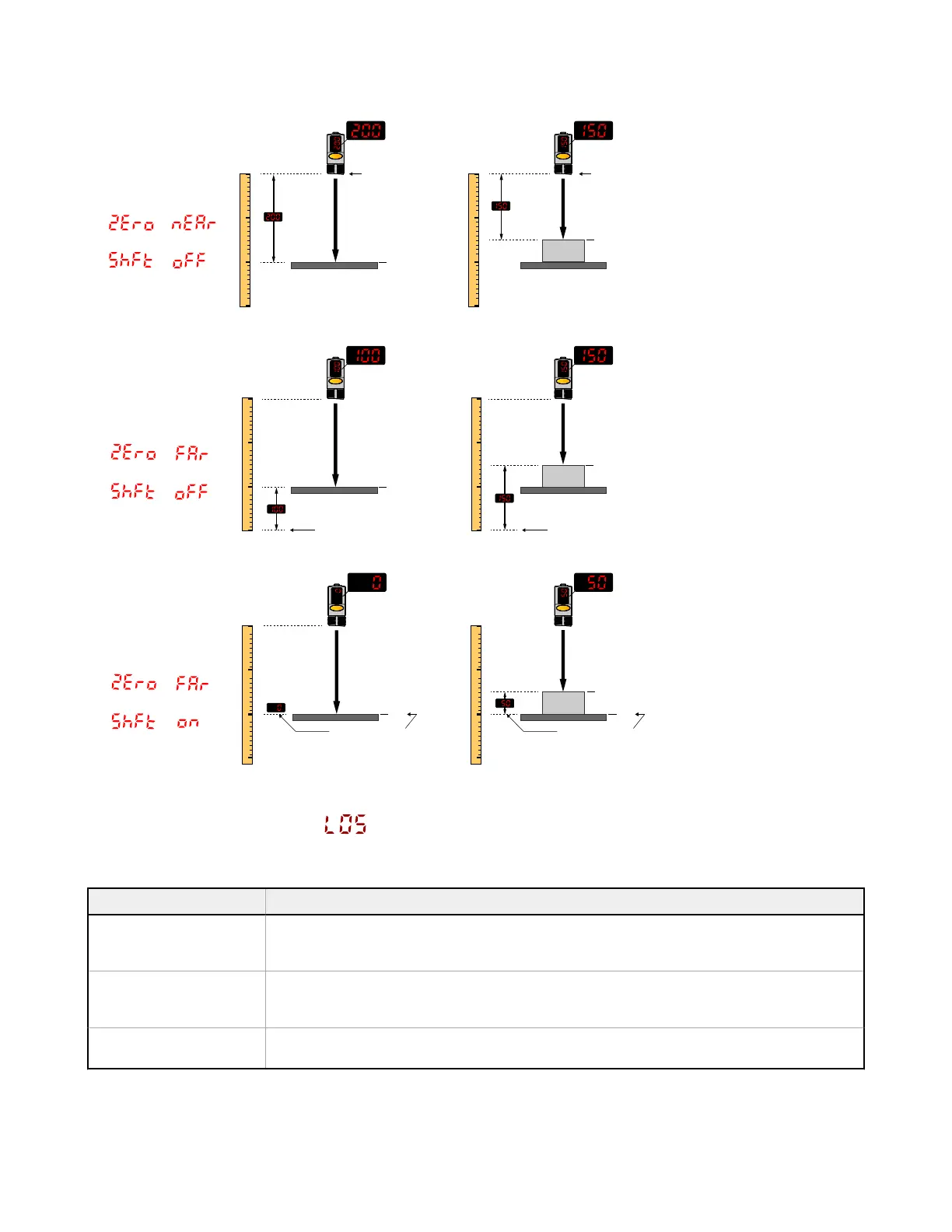
Figure 14. Example Zero and Shift settings
Zero = Near
(Default Setting)
Shift = Off
=
=
Zero = Far
Shift = Off
=
=
Zero = Far
Shift = On
=
=
0 V
0 V
10 V
Display Reference Display Reference
10 V
50 mm
10 V
50 mm
50 mm
Display Reference Display Reference
0 V
Display Reference
100
0
200
300
mm
0
-100
100
200
mm
0
-100
100
200
mm
100
0
200
300
mm
200
0
100
300
mm
200
0
100
300
mm
0 V
Display Reference
3.1.7 Loss of Signal
Use this menu to select the Analog Output value used by the sensor during a loss of signal. When a signal is restored,
measurement resumes. The default is 0 V (4 mA).
Option Description
0 V (4 mA)—default The Analog Output switches to this value 2 seconds after a loss of signal. When advanced
measurements are enabled, the Analog Output is updated to this value immediately upon the
release of the trigger input. For Voltage models, this is 0 V (4 mA). (Default)
10.5 V (20.5 mA) The Analog Output switches to this value 2 seconds after a loss of signal. When advanced
measurements are enabled, the Analog Output is updated to this value immediately upon the
release of the trigger input. For Voltage models, this is 10.5 V (20.5 mA).
Hold The Analog Output holds the last value indefinitely during a loss of signal. When advanced
measurements are enabled, the last value is held across the triggered measurement periods.
Q4X Stainless Steel Analog Laser Sensor
www.bannerengineering.com - Tel: + 1 888 373 6767 13
 Loading...


