2.3 Mount the Device
1. If a bracket is needed, mount the device onto the bracket.
2. Mount the device (or the device and the bracket) to the machine or equipment at the desired location. Do not tighten
the mounting screws at this time.
3. Check the device alignment.
4. Tighten the mounting screws to secure the device (or the device and the bracket) in the aligned position.
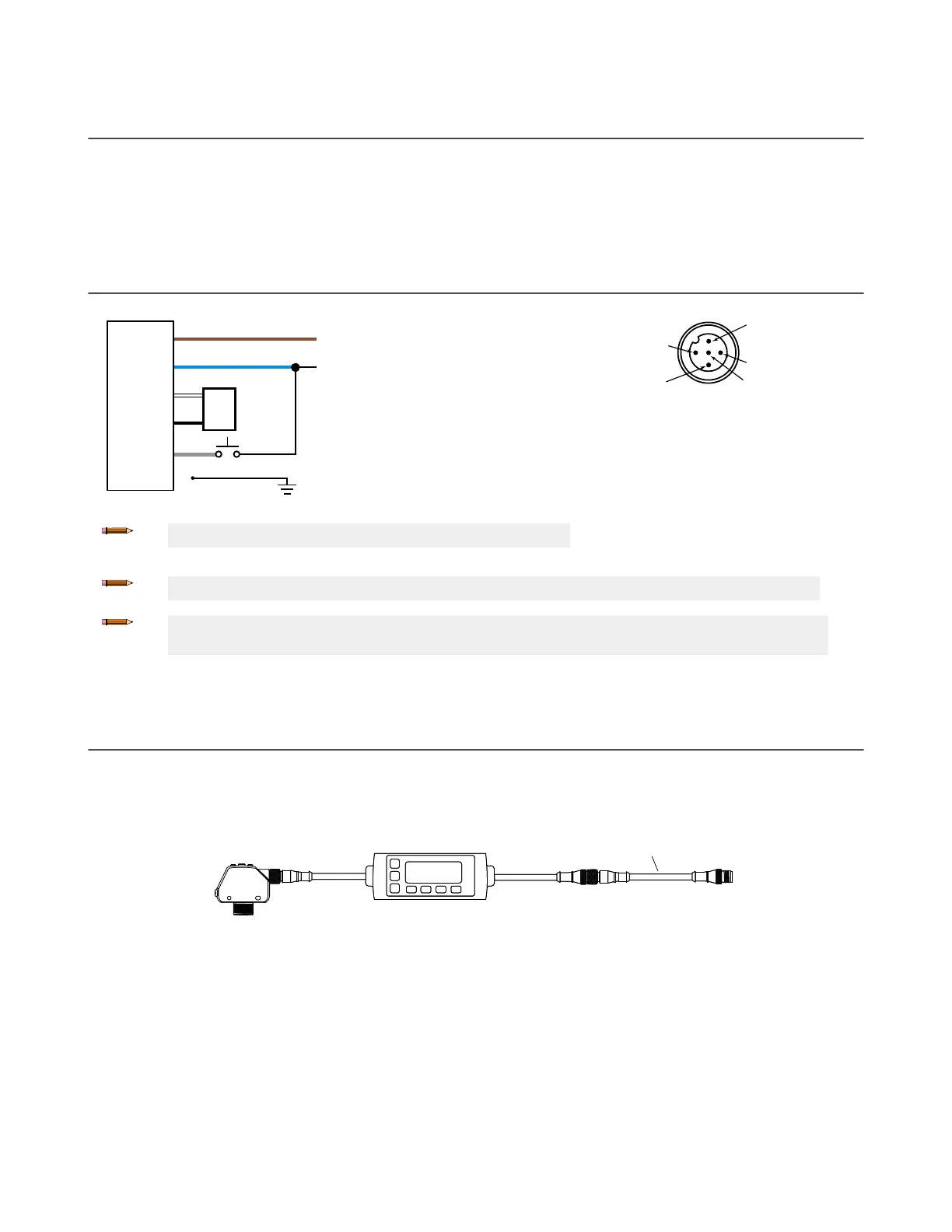
2.4 Wiring Diagram
3
1
2
4
5
12-30V dc
Remote
Teach
Shield
Load
+
–
Analog Out
Analog Gnd
Note: Open lead wires must be connected to a terminal block.
Key
1 = Brown
2 = White
3 = Blue
4 = Black
5 = Gray
Note: The input wire function is user-selectable. The default for the input wire function is off (disabled).
Note: Shielded cordsets are recommended for all models with quick disconnect fittings. It is
recommended that the shield wire be connected to -V dc (the blue wire).
2.5 Connecting to RSD1
The following diagram depicts the connection of the Q4XTULAF600, Q4XTILAF600, Q4XTULAF610, or Q4XTILAF610 to the
optional RSD1 accessory.
Figure 10. Q4X to RSD1
RSD1
Q4X
MQDC-540..SS*
*Optional Extension Cordset: MQDEC3-5..SS
Q4X Stainless Steel Analog Laser Sensor
www.bannerengineering.com - Tel: + 1 888 373 6767 7

 Loading...


