When the sensor is in Run mode, the display shows the current measurement reading or corresponding analog output value.
The size and location of the analog output window can be manually adjusted or the selected TEACH method can be
performed.
When the sensor is in Setup mode, all standard operating parameters, including TEACH mode, analog slope, response time,
and more can be adjusted, or a factory reset can be performed.
1.3 Features
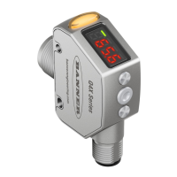
Figure 1. Sensor Features
1. Output Indicator (Amber)
2. Display
3. Buttons
1.3.1 Display and Indicators
The display is a 4-digit, 7-segment LED. The main screen is the Run Mode screen, which shows the current distance to the
target in millimeters.
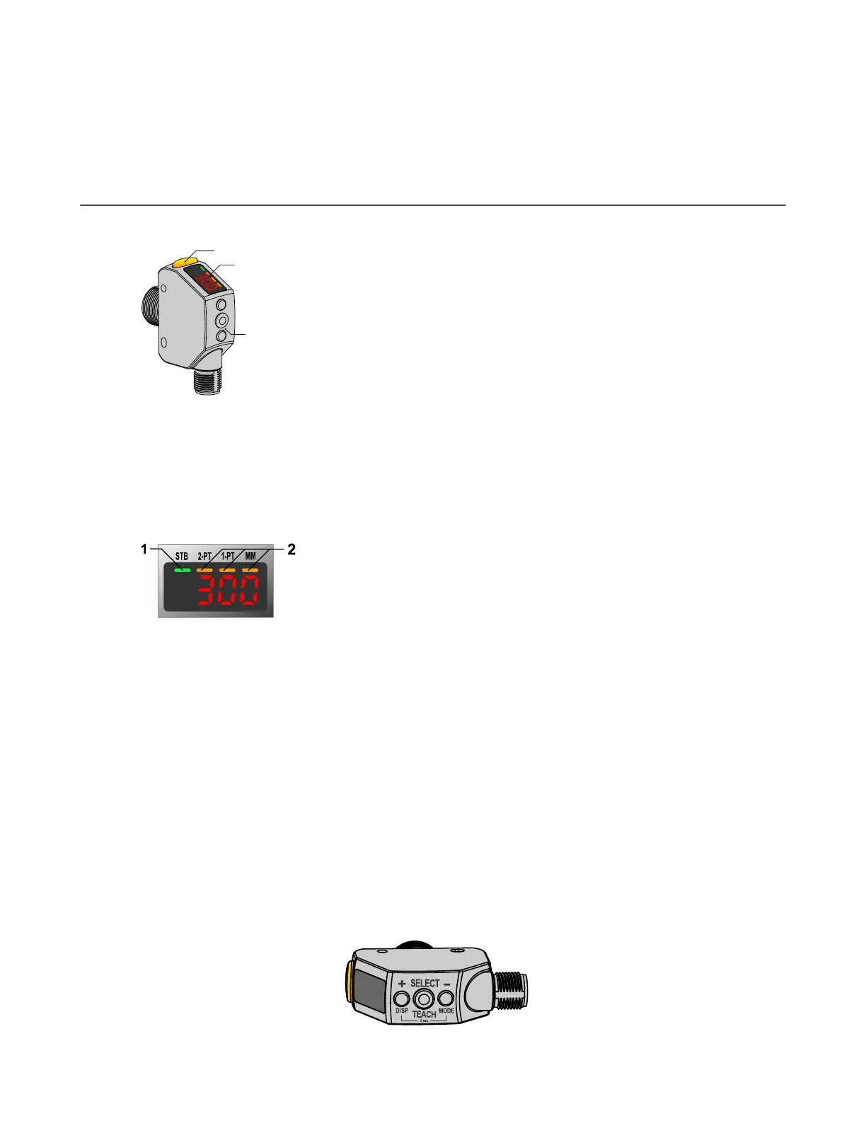
Figure 2. Display in Run Mode
1. Stability Indicator (STB = Green)
2.
Active TEACH Indicators
•
2-PT = Two-Point TEACH (Amber)
•
1-PT = One-Point TEACH (Amber)
3.
Display Value Indicator (MM = Amber)
Output Indicator
•
On—Displayed distance is within the taught analog
output window
• Off—Displayed distance is outside of the taught
analog output window
Stability Indicator (STB)
• On—Stable signal within the specified sensing range
• Flashing—Marginal signal, the target is outside of the
limits of the specified sensing range, or a multiple
peak condition exists
• Off—No target detected within the specified sensing
range
Active TEACH Indicators (2PT and 1PT)
• 2-PT on—Two-point TEACH mode selected (default)
• 1-PT on—One-point TEACH mode selected
Display Value Indicator (MM)
• On—Display shows the distance in millimeters
(default)
• Off—Display shows the analog output value
1.3.2 Buttons
Use the sensor buttons (SELECT)(TEACH), (+)(DISP), and (-)(MODE) to program the sensor.
Q4X Stainless Steel Analog Laser Sensor
4 www.bannerengineering.com - Tel: + 1 888 373 6767
 Loading...


