P/N 133487 115
Banner Engineering Corp. • Minneapolis, U.S.A.
www.bannerengineering.com • Tel: 763.544.3164
SC22-3 Safety Controller
Instruction Manual
Appendix C
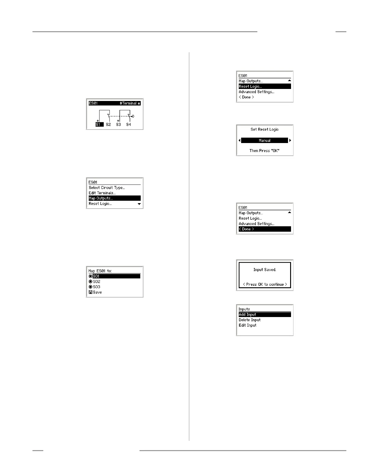
Use the left/right arrow keys to select the terminal assignment to
be changed.
Use the up/down arrow keys to change the terminal
assignments.
Set the terminal assignments to S1, S2, S3, and S4, and press
OK.
After the terminal assignments are edited, the display returns to
the Input Properties menu.
Map Outputs
Choose which of the safety output(s) the input will control. Select
Map Outputs in the Input Properties menu and press OK.
To map the input to an output, select the output using the
up/down arrow keys and press OK. A filled-in circle next to an
output indicates the input is mapped to that output. To remove
the input mapping, select the output and press OK. An open
circle indicates the input is not mapped to that output.
Map the E-stop to all three safety outputs, select Save and press
OK.
After mapping the input to the safety outputs, the display returns
to the Input Properties menu.
Set Reset Logic
To set the reset logic, select Reset Logic and press OK.
Use the left/right arrow keys to select the Set Reset Logic
parameter. Select Manual and press OK.
After the Reset Logic parameter is set, the display returns to the
Input Properties menu.
Saving the Input Device Parameters
All of the E-Stop’s parameters have been set. To save the
parameters, select < Done > and press OK.
The display now indicates the input parameters were saved.
Press OK to continue.
The display returns to the Inputs menu.
 Loading...


