116 P/N 133487
Banner Engineering Corp. • Minneapolis, U.S.A.
www.bannerengineering.com • Tel: 763.544.3164
SC22-3 Safety Controller
Instruction Manual
Appendix C
Adding Other Input Devices
The steps required to add other input devices are similar to
those you’ve just completed.
Now create the following input devices, with properties as
provided in the steps below:
• Gate Switch, GS01
• Two Hand Control, THC01
• Reset Input, RS01
• Optical Sensor, OS01
• External Device Monitors; EDM01, EDM02, and EDM03
• Mute Sensor Pair, M1+M2
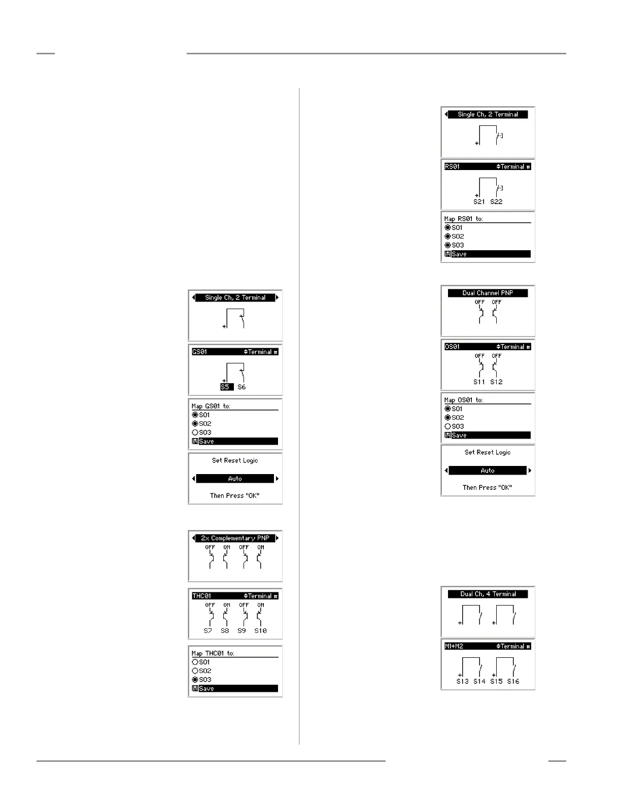
Safety Input: Gate Switch – GS01
Circuit Type:
Single-Channel,
2-Terminal Contact Switch
Terminals: S5 and S6
Mapped to: SO1, SO2
Automatic Reset Logic
Safety Input: Two-Hand Control – THC01
Circuit Type:
2X complementary,
PNP switch
Terminals:
S7, S8, S9, and S10
Mapped to: SO3
Non-Safety Input: Reset Input – RS01
Circuit Type:
Single Channel,
2-Terminal Contact Switch
Terminals: S21 and S22
Mapped to:
SO1, SO2, and SO3
Safety Input: Optical Sensor – OS01
Circuit Type:
Dual-Channel, PNP
Terminals: S11and S12
Mapped to: SO1and SO2
Automatic Reset Logic
Safety Input: Mute Sensor – M1 + M2
The next input is a little different than the previous inputs
added. So, we’ll discuss this one in a little more detail.
After selecting to add a mute sensor and entering its
name, set the circuit type and the terminal assignments
as follows:
Circuit Type:
Dual-Channel Contact Switch
Terminals: 13, 14, 15 and
16
Instead of mapping to an output, mute sensor inputs are
mapped to the inputs they will mute. Only certain types of input
devices can be muted. The Safety Controller creates a list of the
 Loading...


