Procedure of the commissioning
Instruction handbook b maXX (BM4-F-)AIO-XX (Analog IO module)
Document No.: 5.01045.08 Baumüller Nürnberg GmbH
52
of 82
8.2
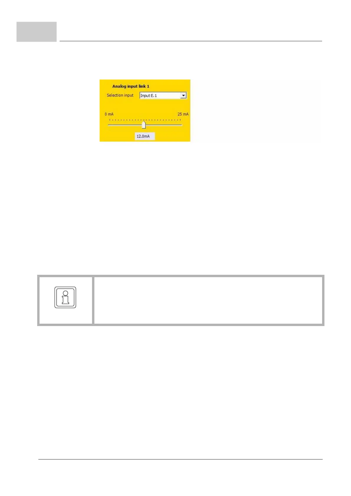
3 By clicking on the g-symbol, select the entry „Input E.1“ („E“ ⇒ module in position E,
„1“ ⇒ input 1) from the drop-down list
.
Figure 18: Input selection AIO-04
4 Enter in menu „Analog input link 1“ :
m Target parameter number: „1171“, (ramp function generator input)
m Smoothing time: „10 ms“,
m Scaling factor: „1“,
m Offset: „0“,
m Threshold: „0“,
A scale is displayed and shows the applied current (set by the current calibrator), e. g.
+12
mA.
5 Check the display in „Analog input link 1“.
The RPM of the motor can be regulated now by the current calibrator.
6 Repeat the above steps for the input 2.
NOTE!
If for example, the scale shows 0 mA, even though there is a current applied on input
1 (see pin assignment
ZConnection diagrams– on page 39), then the input is defec-
tive. When changing the applied current, the relevant value of the current must be dis-
played on the scale.
 Loading...

