Procedure of the commissioning
Instruction handbook b maXX (BM4-F-)AIO-XX (Analog IO module)
Document No.: 5.01045.08 Baumüller Nürnberg GmbH
54
of 82
8.2
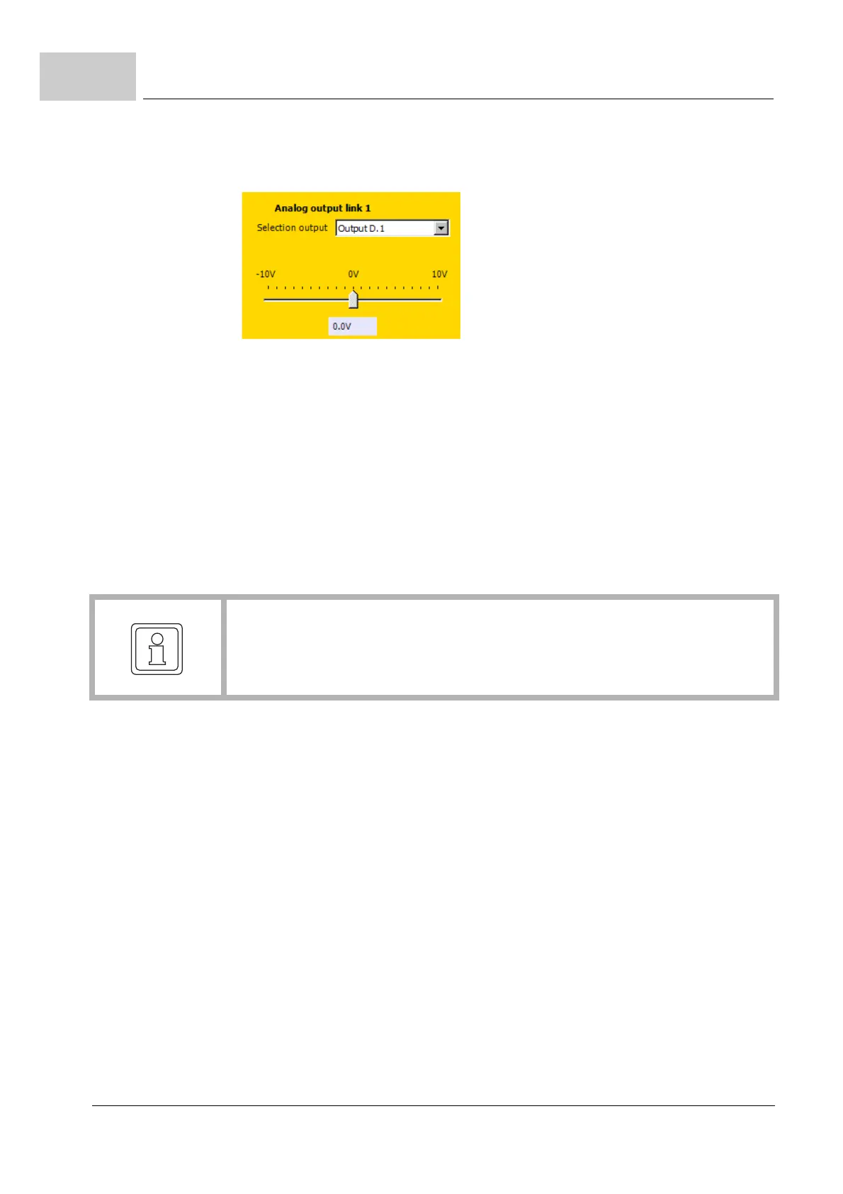
3 By clicking on the g-symbol, select the entry „Output D.1“ („D“ ⇒ Analog IO module
in position D, „1“ ⇒ output 1) from the drop-down list.
Figure 21: Output selection
4 Enter in menu Analog output link 1:
m Source parameter: „1171“,
m Offset: „0 dig“,
m Shift factor: „0“,
m Scaling factor: „1638 Dig/V“.
The voltage at the output point D.1 (see pin-assignment, ZConnection diagrams– on
page 39) can be measured now by using the suitable measuring instrument. If +10 V has
been applied at the input D.1, then there will also be an output voltage of +10 V at the
analog output.
5 Repeat the test for output 2
With that, testing of the Analog-IO-Module is complete.
NOTE!
If no voltage can be measured at the output 1 (see pin assignment ZConnection di-
agrams– on page 39), even though the voltage is changed at the input 1, then either
the Analog-IO-Module or the controller/controller unit is defective.
 Loading...

