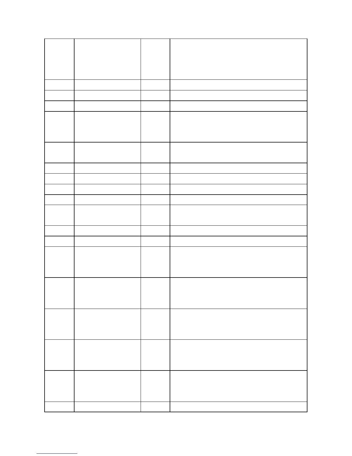
2-9
C0-C7
I,PD
Normal : Digital chroma input
VDAC test DAC test mode [0:7] input.
BIST mode : BIST data input
10 DVDD33 VDD Digital power, 3.3V
11 VCK I Clock of digital video input
12 DVSS GND Digital ground
13-20
Y0-Y7
I, PD
Normal : Digital luma input
VDAC test : DAC test data [0:7] input.
BIST mode : BIST address input
21 SSCK I Normal : Slave serial interface clock input
SCAN mode : scan reset active low
22 SSD IO Slave serial interface data input output
23 DVDD18 VDD Power of digital core, 1.8V
24 PWDN# I, PD Power down, activ e low
25 RST# I, PD Reset, active low.
26 XTAL I Normal : clock input
VDAC test : VDAC test clock input
27 INT O Interrupt output
28 DVSS GND Digital ground
29
A7/GPO0
IO,PD
IO,PD
Power ON : Serial interface address 7
BIST mode : SRAM fail output
Normal : General purpose output
30
A6/GPO1
IO,PD
Power ON : Serial interface address 6
BIST mode : SRAM fail output
Normal : General purpose output
31
TRAP2/GPO2
IO,PD
Power ON : Hardware trap Bit 2
BIST mode : SRAM fail output
Normal : General purpose output
32
TRAP1/GPO3
IO,PD
Power ON : Hardware trap bit
BIST mode : SRAM fail output
Normal : General purpose output
33
TRAP0/GPO4
I
O,PD
Power ON : Hardware trap Bit
BIST mode : SRAM fail output
Normal : General purpose output
MasterI2C on : Master serial interface clock output
- 82 -