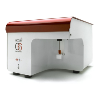
BD Accuri C6 Flow Cytometer Instrument Manual
ii 7820018-01 Rev-2
FIGURES AND TABLES
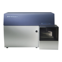
Figure 1-1. The BD Accuri C6 Flow Cytometer System ............................................................. 1
Table 1-3. BD Accuri C6 Flow Cytometer Specifications ............................................................ 2
Table 2-1. Approved Reagents .................................................................................................. 3
Figure 3-1. BD Accuri C6 Flow Cytometer Optics and Fluidics (Top View, Lid Open) ................ 5
Figure 3-2. In-line Sheath Filter ................................................................................................. 7
Figure 3-3. Interference Filter .................................................................................................... 7
Figure 3-4. Fluidics harness ...................................................................................................... 8
Figure 3-5. Proper Attachment of Fluidics Lines ........................................................................ 9
Figure 3-6. Cable Connections .................................................................................................. 9
Figure 3-7 SIP and Sample Stage ............................................................................................10
Figure 3-8. Improper Shut down Message ................................................................................11
Table 4-1. BD Accuri C6 Flow Cytometer Replacement Parts/Reagents List ............................13
Figure 4-1. Automated Preventive Maintenance Notification Window .......................................14
Figure 4-2. Waste Line Quick Disconnect .................................................................................17
Figure 4-3. In-line Sheath Filter ................................................................................................18
Figure 4-4. Peristaltic Pumps and Luer Locks ..........................................................................19
Figure 4-5. Removing Peristaltic Pump Retainer Clip ...............................................................19
Figure 4-6. Sliding Luer Lock Fittings Off of Pump Head ..........................................................20
Figure 5-1. Browse For Folder Dialog Box ................................................................................22
Figure 5-2. Update Driver Software – Cytometer, Second Dialog Box ......................................22
Figure 5-3. Windows Security Window .....................................................................................23
Figure 5-4. Update Driver Software – Cytometer, Successfully updated your driver software ...23
Figure 5-5.The C6 Software Status Message Box – C6 is connected and ready .....................23