Do you have a question about the BD LSR II and is the answer not in the manual?
General description of the BD LSR II flow cytometer and its capabilities.
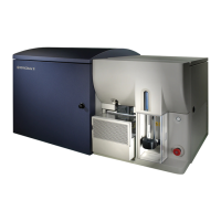
Identification and location of major physical parts of the BD LSR II.
Details on the sample transport and core stream management.
Explanation of the lasers, filters, and detectors in the optics bench.
Information about the computer system controlling the instrument.
Procedure for powering on and connecting the instrument.
Instructions for installing and configuring optical filters.
Steps for filling and managing fluid containers.
Ensuring the fluidics system is ready for operation.
Protocol for monitoring and ensuring instrument performance.
Procedure for optimizing instrument settings for sample analysis.
Steps for acquiring and performing initial analysis of sample data.
Essential requirements for successful DNA analysis.
Preparing the instrument for DNA analysis experiments.
Specific optimization steps for CEN samples.
Method to distinguish singlets from aggregates.
Measuring intracellular calcium ion levels.
Tuning instrument settings for calcium flux experiments.
Procedure for acquiring calcium flux experimental data.
Routine daily procedures for instrument care.
Bi-weekly maintenance tasks for the instrument.
Occasional checks and replacements of instrument components.
Common instrument problems and their recommended solutions.
In-depth explanation of fluid dynamics and hydrodynamic focusing.
In-depth explanation of light scatter and fluorescence.
In-depth explanation of pulse processing and signal digitization.
Template for recording instrument quality control data.
Diagram for noting octagon detector array filter configuration.
Diagram for noting trigon detector array filter configuration.
Catalog information for quality control particles.
Catalog information for necessary reagents.
Catalog information for essential equipment.
Details of the 4-Blue 2-Violet 2-UV 2-Red default optical setup.
Description of common non-standard instrument configurations.
List of frequently used custom instrument configurations.
Diagrams for filter and mirror placement in custom setups.
Software for updating instrument configurations.
Explanation of laser signal timing and alignment.
Steps to align laser signals for optimal detection.
| Type | Flow Cytometer |
|---|---|
| FSC Detector | Photodiode |
| Laser Configuration | 405nm, 488nm, 561nm |
| Detection Channels | Up to 18 |
| Fluorescence Detectors | PMT detectors |
| SSC Detector | PMT detector |
| Forward Scatter Detector | Photodiode |
| Side Scatter Detector | PMT detector |
| Sample Input | Tube sampler, plate loader |
| Data Acquisition Rate | Up to 70, 000 events/second |
| Software | BD FACSDiva |
| Fluidics System | Integrated fluidics system for sample delivery and waste removal |
| Sorting Capability | No |
| Power Requirements | 100-240 VAC, 50/60 Hz |
 Loading...