Commissioning
EL3773 101Version: 2.5
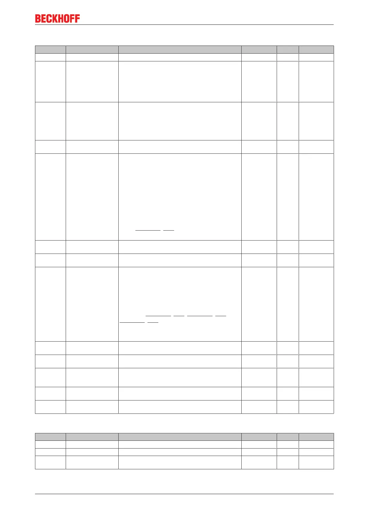
Index 1C33 SM input parameter
Index (hex) Name Meaning Data type Flags Default
1C33:0 SM input parameter Synchronization parameters for the inputs UINT8 RO > 32 <
1C33:01 Sync mode Current synchronization mode:
• Bit 0 = 0: Free Run
• Bit 0 = 1: Synchron with SM 2 Event
• Bit 0-1 = 11: DC with SYNC1 event
• Bit 15 = 1: Fast Mode
UINT16 RW 0x0002 (2
dec
)
1C33:02 Cycle time Cycle time (in ns):
• Free Run: Cycle time of the local timer
• Synchronous with SM 2 event: Master cycle
time
• DC-Mode: SYNC0/SYNC1 Cycle Time
UINT32 RW 0x003D0900
(4000000
dec
)
1C33:03 Shift time Time between SYNC0 event and reading of the inputs
(in ns, only DC mode)
UINT32 RO 0x00000000
(0
dec
)
1C33:04 Sync modes supported Supported synchronization modes:
• Bit 0 = 1: Free Run
• Bit 1 = 1: Synchron with SM 2 Event (Outputs
available
• Bit 2 = 1: DC-Mode (SYNC0)
• Bit 3 = 1: DC-Mode (SYNC1)
• Bit 12 = 1: Legacy Synchron
• Bit 13 = 1: SM event
• Bit 14 = 1: dynamic times (measure by writing
0x1C33:08 [}101])
• Bit 15 = 1: Fast Mode
UINT16 RO 0x0806
(2054
dec
)
1C33:05 Minimum cycle time Minimum cycle time (in ns) UINT32 RO 0x000186A0
(100000
dec
)
1C33:06 Calc and copy time Time between reading of the inputs and availability of
the inputs for the master (in ns, only DC mode)
UINT32 RO 0x00000000
(0
dec
)
1C33:08 Command With this entry the real required process data provision
time can be measured.
• 0: Measurement of the local cycle time is
stopped
• 1: Measurement of the local cycle time is
started
The entries 0x1C33:03 [}101], 0x1C33:06 [}101],
0x1C33:09 [}101] are updated with the maximum mea-
sured values.
For a subsequent measurement the measured values
are reset
UINT16 RW 0x0000 (0
dec
)
1C33:09 Maximum Delay time Time between SYNC1 event and reading of the inputs
(in ns, only DC mode)
UINT32 RO 0x00000000
(0
dec
)
1C33:0B SM event missed
counter
Number of missed SM events in OPERATIONAL (DC
mode only)
UINT16 RO 0x0000 (0
dec
)
1C33:0C Cycle exceeded
counter
Number of occasions the cycle time was exceeded in
OPERATIONAL (cycle was not completed in time or
the next cycle began too early)
UINT16 RO 0x0000 (0
dec
)
1C33:0D Shift too short counter Number of occasions that the interval between SYNC0
and SYNC1 event was too short (DC mode only)
UINT16 RO 0x0000 (0
dec
)
1C33:20 Sync error The synchronization was not correct in the last cycle
(outputs were output too late; DC mode only)
BOOLEAN RO FALSE
Index F000 Modular device profile
Index (hex) Name Meaning Data type Flags Default
F000:0 Modular device profile General information for the modular device profile UINT8 RO > 2 <
F000:01 Module index distance Index distance of the objects of the individual channels UINT16 RO 0x0010 (16
dec
)
F000:02 Maximum number of
modules
Number of channels UINT16 RO 0x0007 (7
dec
)