ConnectionConnection
CC612(4G)_D00325_04_M_XXEN/03.2019
24
5.2.1.11 Connectivity to eHZ or Modbus meters and (optionally) meters with an S0
interface
The use of a meter is not mandatory. However, a meter should be used when
meter readings are required during normal operation. An EMH eHZ meter can be used if
the meter should be digitally read. The meter is read by an optical reader attached to the
mounting plate of the meter so that it can interface with the optical interface on the back
of the meter. The optical reader is then connected to the charge controller with a RJ10
plug.
Modbus RTU can be used instead of an RS-485 based eHZ interface to connect to Modbus
meters. Various Modbus meters are currently supported, including:
• ABB B23 series
• Eastron SDM120 series
• Eastron SDM230 series
• Eastron SDM630 series
• Garo GNM1D
• Garo GNM3D
• Finder 7E.78.8.400
• Saia ALE3
Additional Modbus meters can be added upon customer request and may be added with
each software release. Supported Modbus meters are listed on the webserver Operator
tab.
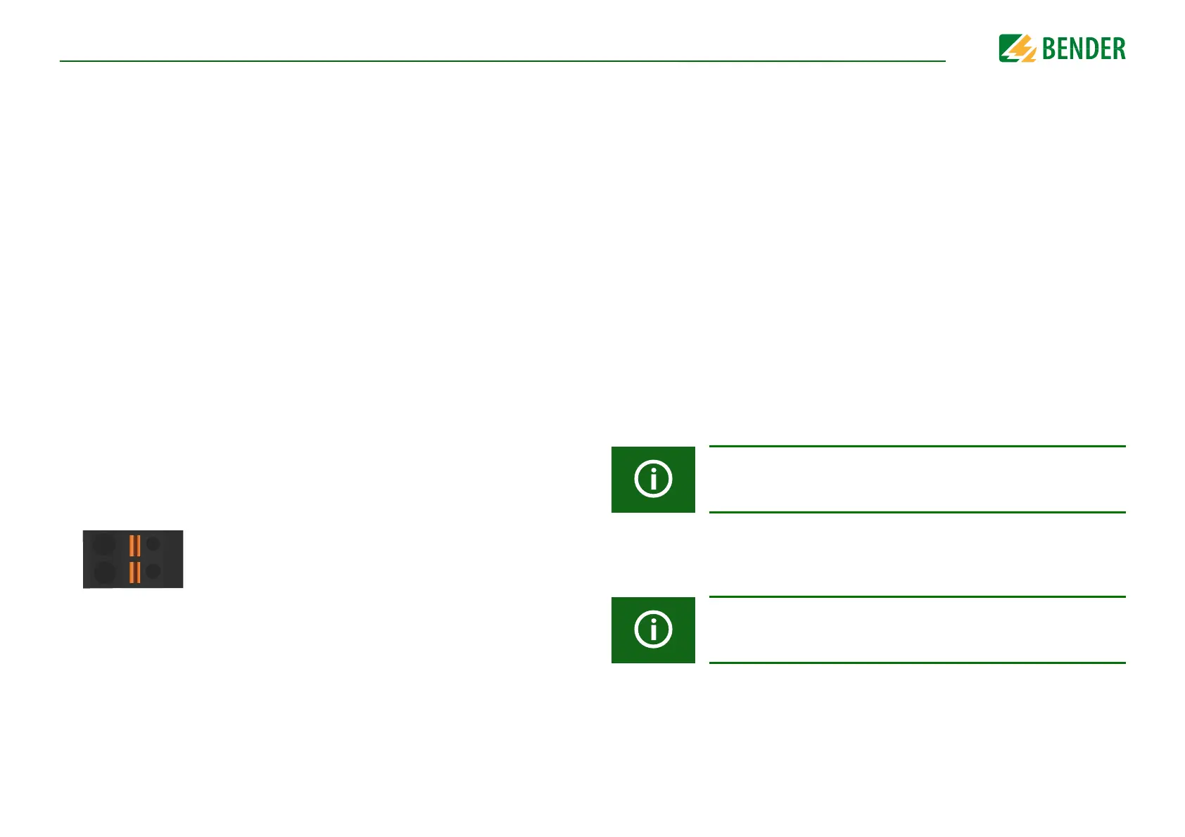
The Modbus meter interface on the charge controller is shown below:
A
B
The system periodically queries the relevant registers of the Modbus meters and uses the
meter values to fulfill the charge controller functionality. Depending on support by the
meter, current, voltage and power are also obtained directly from the meter as opposed
to being calculated based on the increasing energy amounts reported. If meter readings
are required, the baud rate and the slave ID need to be configured directly on the Modbus
meter as follows:
• Baud rate: 9,600 Bd
• Slave ID: 1
• 8N1 (8 data bits, no parity, 1 stop bit)
• For Saia ALE3: 8E1 (8 data bits, even parity, 1 stop bit)
The charge controller can optionally read meters with an S0 interface. These meters can
be attached to one of the available inputs (see Page 18).
5.2.1.12 User interface connection
The charge controller features a simple user interface for customer-specific applications.
This interface can connect to the:
• RFID module RFID110-L1 - The RFID module is a separate PCB with status and ligh-
ting LEDs and is designed according to ISO14443A/MIFARE. It is connected to the
charge controller using a standard RJ45 cable.
• RFID module RFID114 - The RFID module is a separate PCB without status and ligh-
ting LEDs and is designed according to ISO14443A/MIFARE. It is connected to the
charge controller using a standard RJ45 cable.
The RFID module is described in a separate operating manual (docu-
ment number D00283), which can be downloaded from
www.bender.de/en/service-support/downloads.
The RFID module is described in a separate operating manual (docu-
ment number D00328), which can be downloaded from
www.bender.de/en/service-support/downloads.