FunctionFunction
CC612(4G)_D00325_04_M_XXEN/03.2019
9
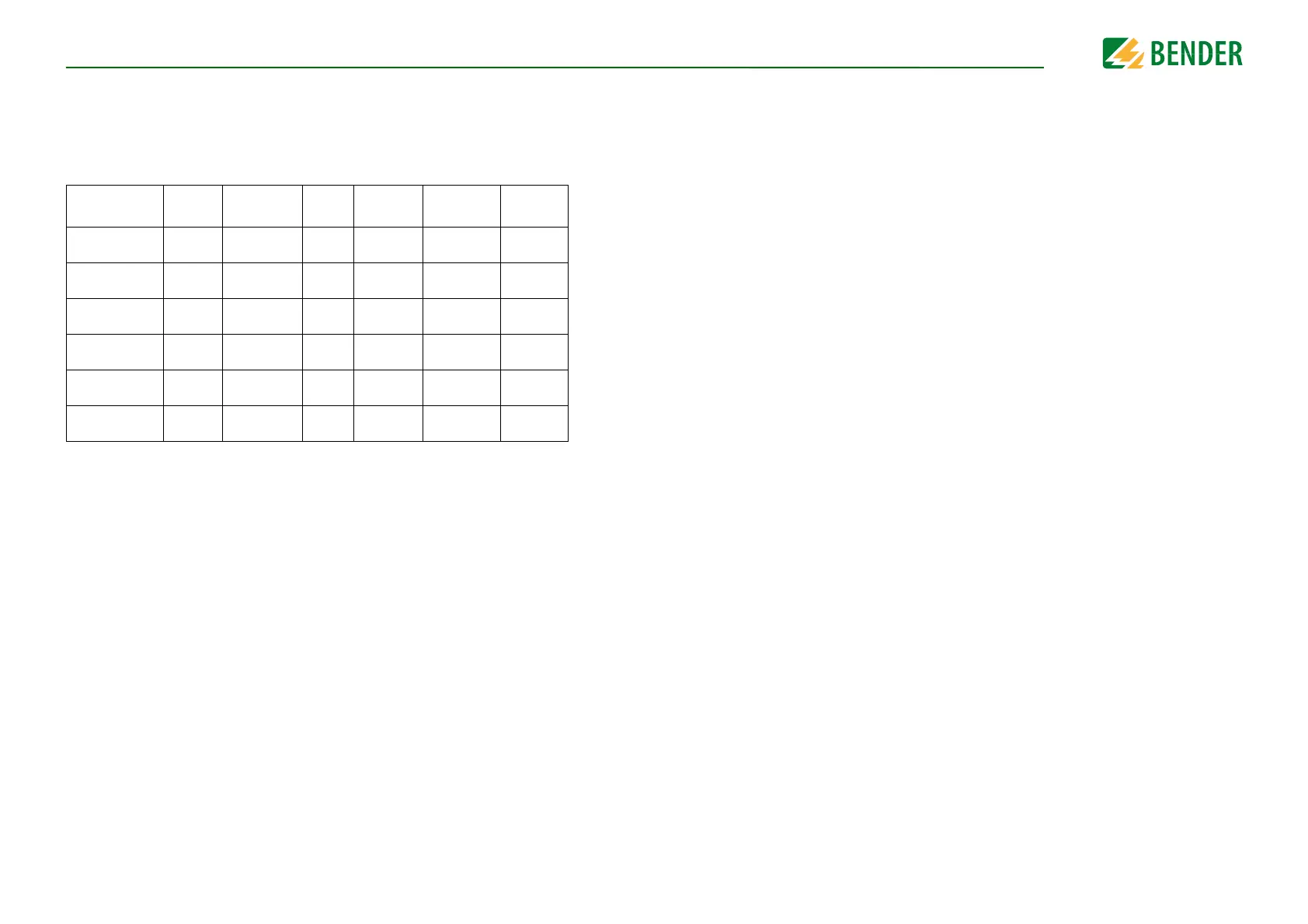
3.2.1 Product variant overview
Several product variants are available and the table below gives an overview of these variants.
Some connect to a digital eHZ meter using an optical interface while others read Modbus me-
ters. In general, variants can read meters with an S0 interface. Ordering details can be found
on Page 44
.
* Optional and enabled by a software update
Type Modem Meter
RDC-
MD*
PLC*
hardware
LEDs
User
interface
CC612 -1M4PR 4G
eHZ and S0
interface
Ready,
Alarm, PLC
CC612 -2M4PR 4G
Modbus, S0
interface
Ready,
Alarm, PLC
CC612 -1S0PR ---
eHZ and S0
interface
Ready,
Alarm, PLC
CC612 -2S0PR ---
Modbus, S0
interface
Ready,
Alarm, PLC
CC612 -2M4R 4G
Modbus, S0
interface
---
Ready,
Alarm
CC612 -2S0R ---
Modbus, S0
interface
---
Ready,
Alarm
3.3 Functional description
As well as the charge controller, a charging system also consists of a type A RCD, a relay
contactor, which is directly connected to a type 1 or type 2 socket, or to an attached cable
with a type 1 or type 2 plug. These essential components are shown in Chapter 3.3.2.
3.3.1 General functions
• A charging system may also consist of a meter, and if the meter should be read digi-
tally, either a smart digital meter (EMH eHZ) or a digital Modbus meter is required.
• The charge controller reads the digital eHZ meter readings using a standard opti-
cal reader attached to the charge controller via an RJ10 plug.
• If the Modbus version is used, the Modbus wires are attached directly to the
charge controller.
• Alternatively, any meter with an S0 interface can be attached to one of the availa-
ble inputs.
• A 12 V power supply is needed to operate the charge controller and an RFID module
can be used to facilitate simple user interaction. The RFID module is a separate PCB
and is connected to the charge controller using a standard RJ45 cable.
• Power flow toward the vehicle is controlled by the contactor (using a signal voltage
of up to 30 V), which is itself controlled by the the charge controller via a relay in the
charge controller.
• The SIM card slot (available on charge controller Master variants only) is positioned
on the charge controller front panel. The SIM card can have a PIN number which can
be configured via an internal configuration web interface. The APN settings for the
card can also be configured via an internal configuration web interface.
• Also positioned on the front panel are two USB interfaces:
• The first known as CONFIG is used to configure the charge controller. Optionally,
this interface can also be used to apply software updates.
• The other USB interface allows the connection of peripheral USB devices.
• Both USB interfaces are used to enable a Master/Slave connection. Master/Slave
operation is configured by connecting the USB configuration interface (CONFIG)
of the data gateway with 4G modem to the Ethernet/USB WLAN interface of the
data gateway without 4G modem using a USB cable. Refer to Page 17 for further
information.
• Only the front panel of data gateways with 4G modem variants features a connec-
tion for a 4G antenna.