FunctionFunction
CC612(4G)_D00325_04_M_XXEN/03.2019
12
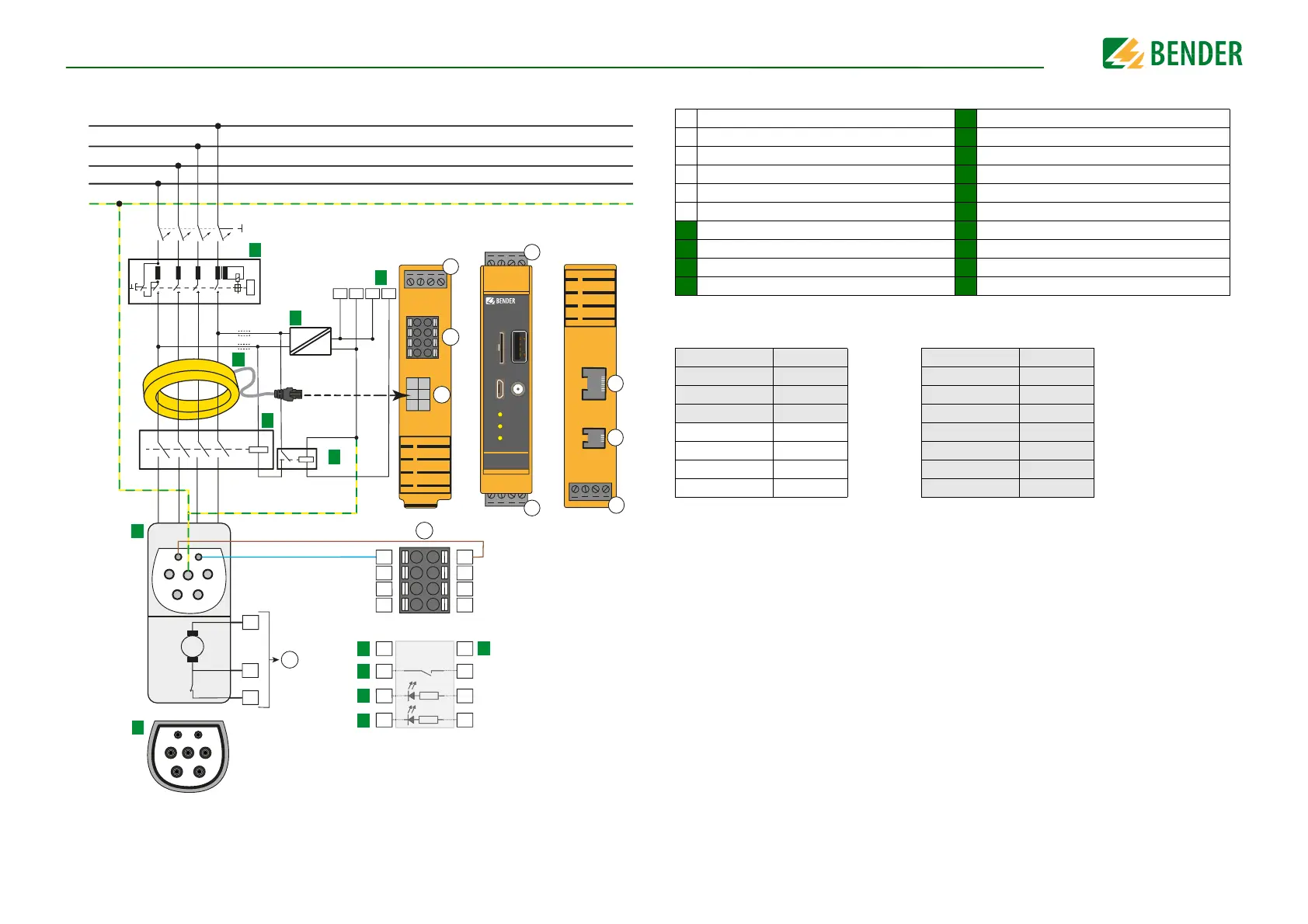
3.3.3 Charging system with a type 2 socket and an intermediate relay
–
+
IN
M
–
+
A
CP
PP
PE
N L1
L2
L3
e
L1
L2
L3
N
PE
k
PP
CP
PE
L1 N
L3
L2
f
12V 0V 11 14
B
1
2
3
4
5
6
D
C
A
RJ10
F
RJ45
E
CC612
ALARM
READY
PLC
USB 1
SIM
CONFIG
B
A
PP
IN1–
IN2–
21
IN1+
IN2+
CP
24
C
IN2–
IN2+
n
IN1–
IN1+
m
21
24
j
PP
CP
g
h
–
OUT + IN
14
11
0V
12V
i
AC
DC
0 V
12 V
b
c
d
H
V
a
CC612 Charge Controller
Bottom view
Frontal view
Top view
Mennekes
Type 2 socket *
Legend
Assignment of the terminals
A Connection locking engine d Contactor
B Connection socket User Interface
e Type 2 socket*
C Connection socket
f Type 2 plug*
D Connection Current Transformer (CT)
g Connection Proximity Pilot
E Terminal User Interface (RJ45)
h Connection Control Pilot
F Terminal Modbus/eHZ meter (RJ10)
i Relay 1: Control pin intermediate relay
a RCD Type A j Output relay 2
b Voltage supply DC 12V k Intermediate relay
c Current Transformer (CT) with plug m Optocoupler input 1
n Optocoupler input 2
A1 IN C1 PP
A2 + C2 CP
A3 OUT C3 21
A4 - C4 24
B1 12V
C5 IN1-
B2 0V
C6 IN1+
B3 11
C7 IN2-
B4 14
C8 IN2+