ConnectionConnection
CC612(4G)_D00325_04_M_XXEN/03.2019
16
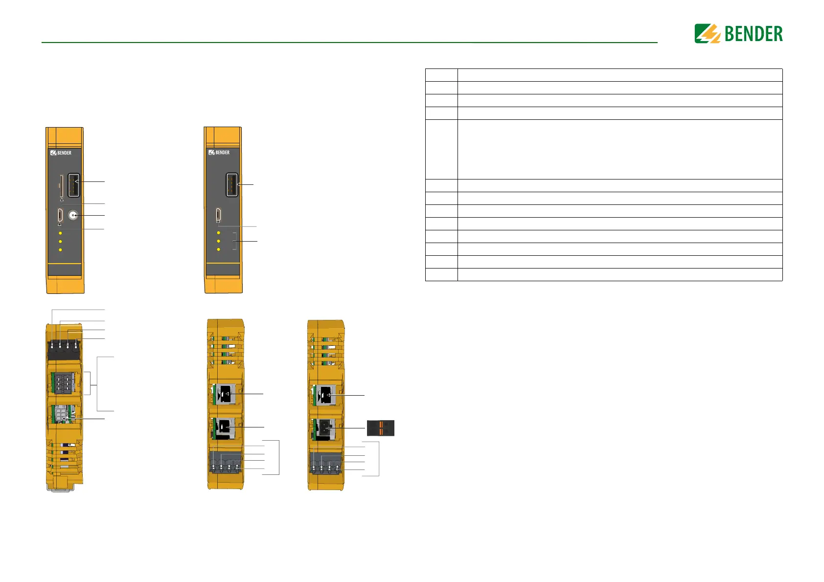
5.2 Connectivity
The charge controller connections for all device variants are shown below.
2
CC612
ALARM
READY
PLC
USB 1
SIM
CONFIG
3
1
4
4
5
SIM
CC612
ALARM
READY
PLC
USB 1
CONFIG
1
11
12
13
13
A
B
11
6
7
10
IN1-
24
IN1+
9
8
12V 0V 11 14
PP
CP
IN2-
IN2+
21
Bottom view
Data gateway (with modem)
Data gateway (without modem)
Frontal view
Top view
Variant with eHz meter
Top view
Variant with Modbus meter
PP
CP (additionally with PLC)
Relay 2
Relay 2
IN1-
IN1+
IN2-
IN2+
(-)
OUT
(+)
IN
(-)
OUT
(+)
IN
Legend:
1 USB interface for Ethernet/WLAN/connection to Master
2 SIM card slot
3 Antenna socket
4 Configuration interface/connection to Slave
5
LEDs for:
• ALARM
• READY (Online connectivity)
• PLC (Power Line Communication) - Optional
6 12 V power supply
7 0 V
8 Relay 1 (Control voltage contactor)
9 Relay 1 (Contactor control pin)
10 Connection current transformer (optional)
11 Connection to user interface via RJ45 cable
12 Meter connection
13 Plug lock connections