Serial interfaces
74
IRDH375_D00124_05_M_XXEN/01.2020
Faults may be caused when:
Addresses are assigned twice
A second Master exists on the BMS bus
Interference signals occur on the bus lines
A defective device is connected to the bus
Terminating resistors are not activated
7.4.2 BMS Slave
All IRDH375B are factory set to Slave mode (address 3). In a BMS network, one
address must be selected from the address range 2…30 for each Slave. There
may be no gaps of more than five subsequent addresses, so that all Slaves can
be scanned by the Master. For IRDH375B a BMS address can be selected from
the address range 1 … 30. When assigning the addresses, also other devices
such as the EDS47x-12 must be considered.
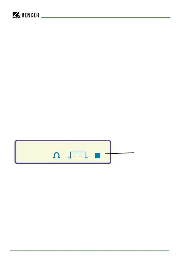
The correct reception of BMS data is indicated by a flashing point on the dis-
play on the right of the measuring pulse indication.
Flashing point:
BMS data re-
ceived
If no flashing point appears, it may be attributed to the following:
No Master available in the network
More than one Master available in the network
RS-485 interface (terminal A/B) not connected or reversed