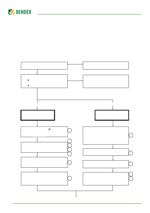
4. Commissioning flow chart (threepart)
Is the system to be monitored an
unearthed system (IT system)?
The IRDH375 is not suitable for this
application( contact BENDER).
U
n
is too high for direct
connection. A coupling device
providing the respective voltage
range must be connected.
Device connection
Optional device
connection
no
no
yes
The terminals L1 and L2 must be
connected to U
n
of the system to be
monitored according to the wiring diagram.
An external kW measuring instrument
at M+/M- with a display range of
10 kW...1000 kW,
Scale centre point: 120 kW
Output current IRDH375: 0...400 mA
Output current IRDH375B: 0/4...20 mA
Connect the supply voltage Us
to the terminals A1/+ and A2/-. Consider
the details indicated on the nameplate.
External TEST button (NO contact) to the
terminals T1 and T2
External RESET button (NC contact) to the
terminals R1 and R2
The output contacts of the alarm relays
System fault (31-32-34)
Alarm 1 (11-12-14)
Alarm 2 (21-22-24)
When using the RS485 interface, take care
that a 120 W resistor is connected at
the beginning and the end of the network.
Terminate IRDH...: S1 = ON
13
12
11
7
8
10
Deenergize the installation
before connecting the device!
Recommended wire cross section of
connecting cable
single wire 0.2...4 mm
2
flexible 0.2... 2.5 mm
2
Is the maximum nominal voltage
U
n
AC 793 V
or
U
n
DC 650 V
yes
The two PE connections
and KE must
be connected separately to the
equipotential bonding.
6
2
3
4
5
1