115
6 - PARAMETER DESCRIPTION
P58 Analog Input Span I/O 11
LED Display LCD Display
Range 1 – 100% (Default 100%)
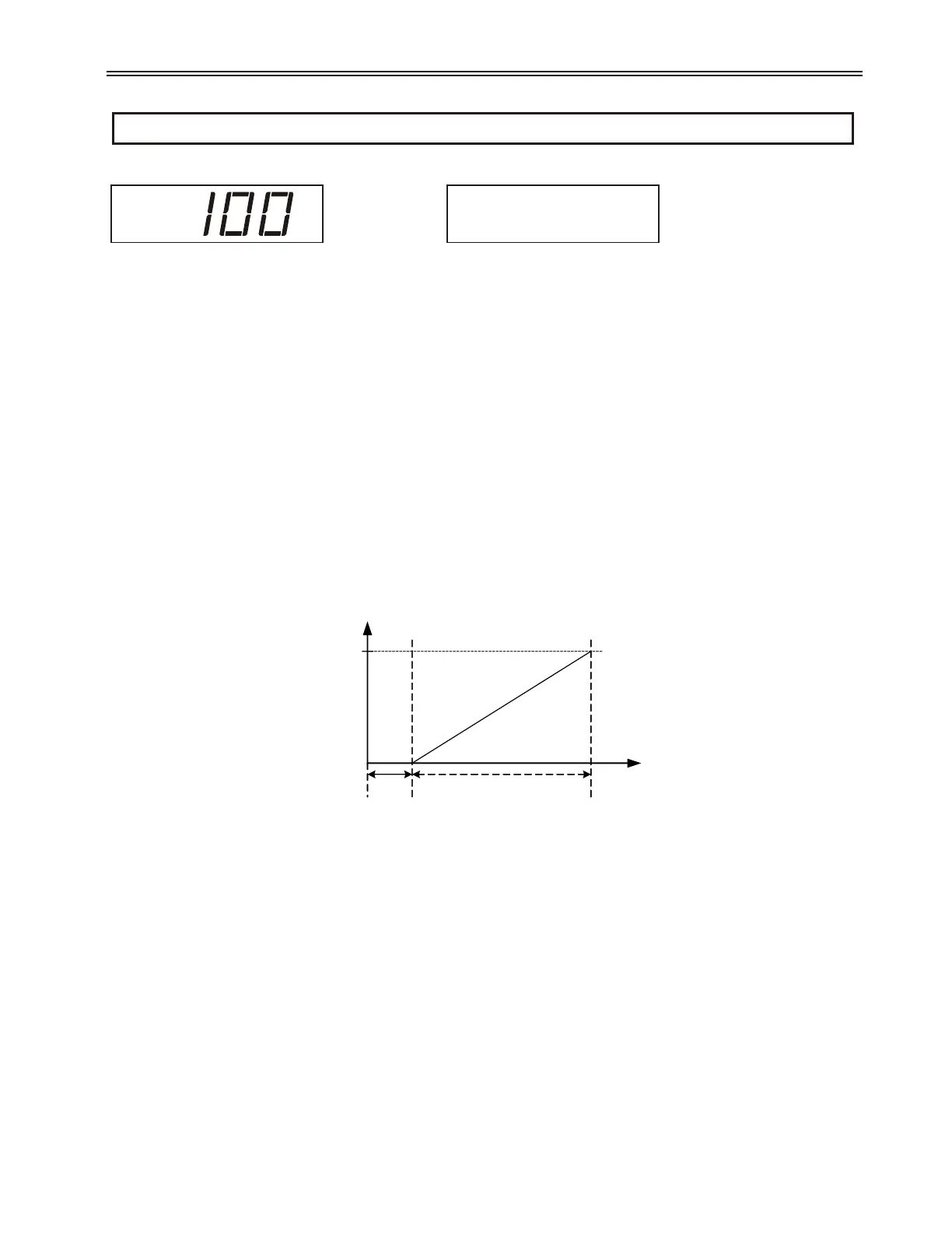
Description The analog input can be scaled using the Analog Input Span parameter.
Examples:
For a 0-10V input or 0-20mA input, a 100% Analog Input Span setting results in a 0% input reading with a
0V input and a 100% input reading with a 10V input.
For a 0-5V input, a 50% Analog Input Span setting results in a 0% input reading with a 0V input and a 100%
input reading with a 5V input.
For a 4-20mA input, a 80% Analog Input Span setting and a 20% Analog Input Offset setting results in a 0%
input reading at 4mA and a 100% input reading at 20mA.
z NOTE: The DIP switch (SW1) on the card changes the analog input and analog output between 0-10V or
0-20mA. See Figure 18 to see DIP Switch Settings. ANALOG INPUT SW1-1 ANALOG OUTPUT SW1-2.
z NOTE: Input signal readings are clamped at a 100% maximum.
Example: 4ma = 0% input, 20ma = 100% input
See Also Analog Input Trip Level (P56 / I/O 09) parameter on page 114.
Analog Input Trip Time (P57 / I/O 10) parameter on page 114.
Analog Input Offset (P59 / I/O 12) parameter on page 116.
Starter Type (P74 / FUN 07) parameter on page 124.
Theory of Operation section 7.11, Phase Control on page 165.
Theory of Operation section 7.12, Current Follower on page 167.
I/O: Ain Span
11 100 %
Analog Input
Reading %
100%
Ain Span = 80%
2V / 4mA
0%
20% Ain
Offset
10V / 20mA
Input Signal
 Loading...