42
3 - INSTALLATION
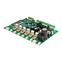
3.9.4 Analog Input
The analog input can be configured for voltage or current loop. The input is shipped in the voltage loop configuration unless specified in
a custom configuration. Below TB5 is SW1-1. When the switch is in the on position, the input is current loop. When off, it is a voltage
input. The control is shipped with the switch in the off position. See Figure 18.
z NOTE: The analog input is a low voltage input, maximum of 15VDC. The input will be damaged if control power (115VAC) or line
power is applied to the analog input.
The terminals are as follows:
1 ) +10VDC Power (for POT)
2 ) + input
3 ) - input
4 ) common
7 ) shield
See Also Analog Input (I/O 08 - 12) on page 113.
Starter Type parameter (FUN 07) on page 124.
Theory of Operation section 7.11, Phase Control on page 165.
Theory of Operation section 7.12, Current Follower on page 167.
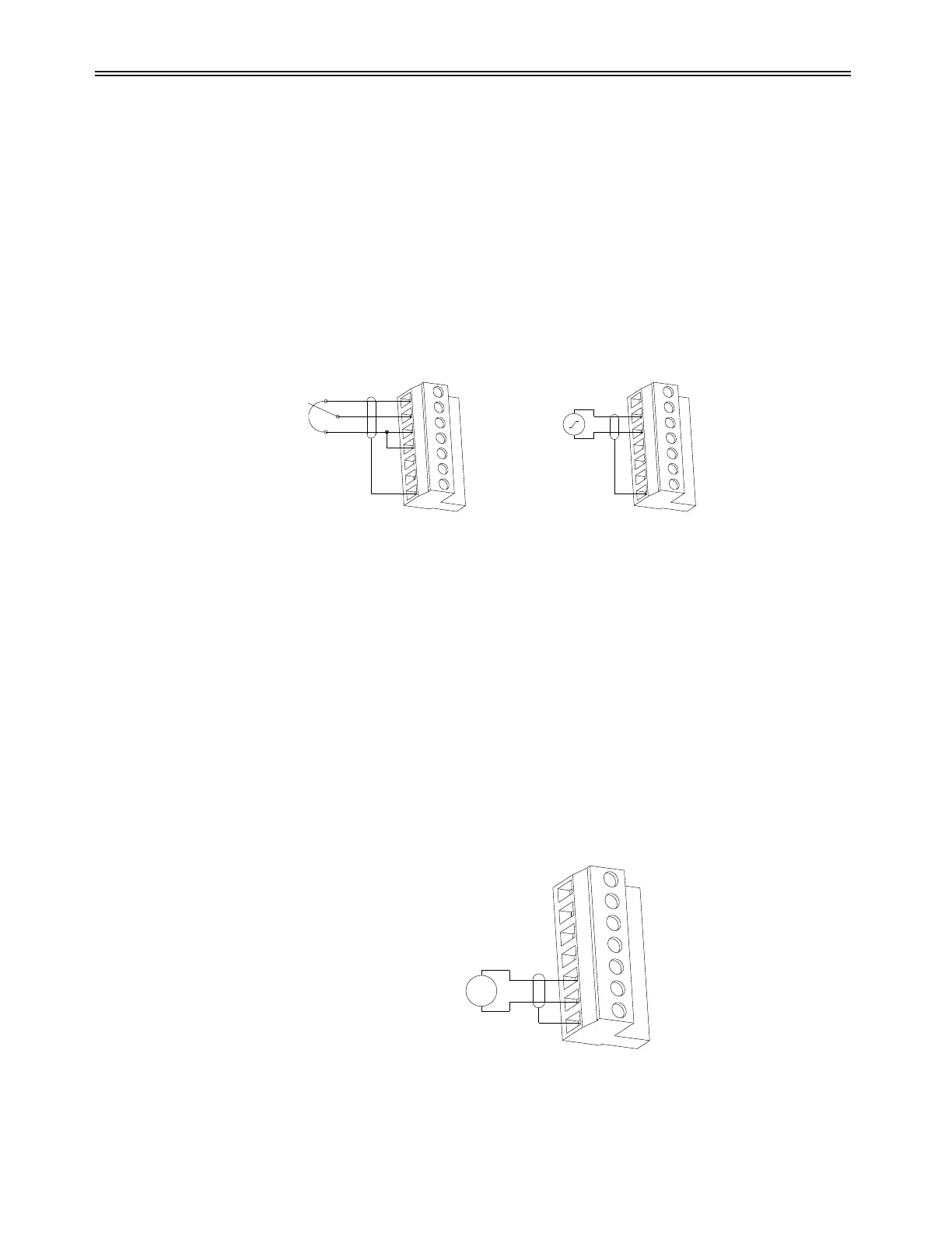
3.9.5 Analog Output
The analog output can be configured for Voltage or Current loop. The output is shipped in the Voltage loop configuration unless
specified in a custom configuration. Below TB5 is SW1-2. When the switch is in the off position, the output is current. When on, it is a
Voltage loop output. The control is shipped with the Switch on. See Figure 18.
z NOTE: The analog output is a low voltage output, maximum of 15VDC. The output will be damaged if control power (115VAC)
or line power is applied to it.
The terminals are as follows:
5 - analog output
6 - common
7 - shield
See Also Analog Output configuration (I/O 13 - 15) on page 116.
(5K-10K ohm)
POTENTIOMETER 4-20mA
4-20mA SOURCE
+
-
TB5 TB5
Figure 16: Analog Input Wiring Examples
V/I
TO METER / ANALOG INPUT CARD
+
-
TB5
Figure 17: Analog Output Wiring Example
 Loading...