Control Wiring
3.9 Control Wiring
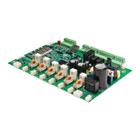
3.9.1 Control Power
The 120VAC control power is supplied to TB1. The connections are as follows:
1 - Ground
2 - Neutral
3 - Neutral
4 - Line (120VAC)
5 - Line (120VAC)
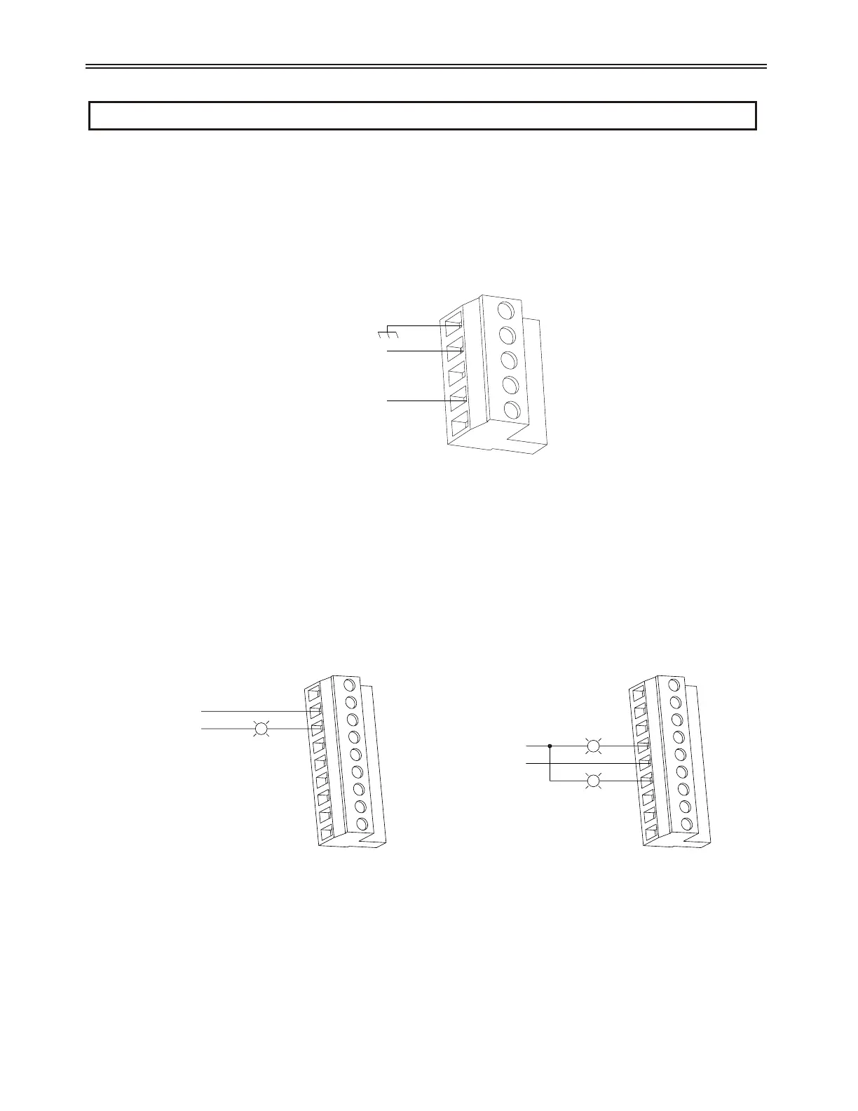
3.9.2 Output Relays
TB2 is for the output relays. The relays connect as follows:
1 - NO1: Relay 1 normally open
2 - RC1: Relay 1 common
3 - NC1: Relay 1 normally closed
4 - NO2: Relay 2 normally open
5 - RC2: Relay 2 common
6 - NC2: Relay 2 normally closed
7 - NO3: Relay 3 normally open
8 - RC3: Relay 3 common
9 - NC3: Relay 3 normally closed
See Also Relay Output configuration (I/O 05 - 07) on page 112.
40
3 - INSTALLATION
120VAC LIVE
120VAC NEUTRAL
TB1
Figure 13: Control Power Wiring Example
120VAC LIVE
120VAC NEUTRAL
TRIP
TRIP PILOT LIGHT
(RELAY 1 SET TO FLFS - FAULT FAILSAFE)
120VAC LIVE
120VAC NEUTRAL
STOP
RUN & STOPPED PILOT LIGHT
(RELAY 2 SET TO RUN)
RUN
TB2 TB2
Figure 14: Relay Wiring Examples
 Loading...