132
7 - PARAMETER DESCRIPTION
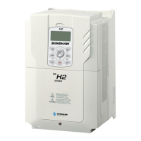
Ride-Thru Enable AFN 58
AFN: Ride-Thru En
58 w/ LVT
LCD Display
Range
Parameter
Value
Description Tracing
Ride-Thru
mode
UV
Fault
Disabled
- Under Voltage Ride-Thru state is disabled. Once the bus voltage system goes to the ready
state, the drive will not stop.
- Only mode that does not enter the ride-thru or ride-thru timeout bus monitoring states.
- Disables both the Ride-Thru mode and Tracking.
Disable Disable Disable
w/ LVT
(Default)
- The bus voltage system will adjust the voltage level (thresholds) based on the long term
average of the bus voltage.
- Only mode that uses the tracking system.
Enable Enable Enable
w/o LVT
- Disables the voltage tracking system.
- The default levels dene when the bus voltage system change to various states (Ride-
Thru, ride-thru timeout, under voltage, etc)
Disable Enable Enable
No UV
Fault
- Same as “w/o LVT” except if the bus recovers from the ride-thru timeout state then the
under voltage fault is not generated.
- The bus voltage system will reset and go back thru the startup sequence.
Disable Enable Disable
Description This parameter allows the function to disable either (a) undervoltage ride-through or (b) continuous Line
Voltage Tracking (LVT) that produces dynamic Undervoltage Ride-Thru Thresholds.
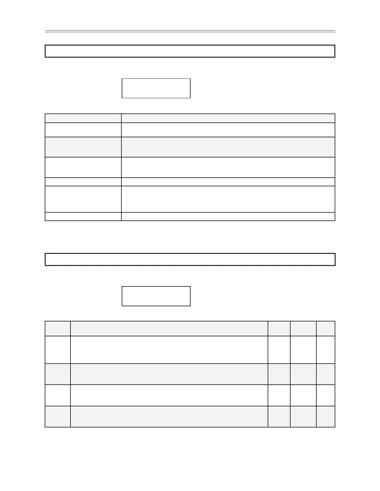
PowerFailCongAFN57
AFN: Pwr Fail Cfg
57 CTS No Msg
LCD Display
Range
Parameter Name Description
CTS No Msg (Default)
When the parameter is set to this value in the Vector or Linear-Auto modes the drive will simply coast to
stop when an UnderVoltage condition (Power-down) is detected.
Coast Stop
When the parameter is set to this value in the Vector or Linear-Auto modes the drive will simply coast to
stop when an UnderVoltage condition (Power-down) is detected. In this mode, however, the drive will
fault with an UnderVoltage. This will register the powerdown in the fault log.
Ramp Down
When power is lost in the Vector or Linear-Auto modes with this setting, the drive will ramp the motor
down at a decel rate of Decel 1. When the drive is fully ramped down, the drive will fault with an Under-
Voltage. If the power recovers the drive will continue to ramp to stop and fault
Quick Ramp Same as “Ramp Down” above except the shortest ramp is chosen between ‘Decel 1” and “Decel 2”.
Controlled
When power is lost in the Vector or Linear-Auto modes with this setting, the drive will decelerate the
motor trying to regulate the bus voltage to the UnderVoltage level. If the power recovers, the drive accel-
erates to the command frequency without faulting the drive. If the drive reaches the stopped condition, it
will generate an UnderVoltage fault.
Control No Msg Same as the “Contolled” mode but without generating and UnderVoltage fault.
Description This parameter can be used to dene how the drive responds to an undervoltage operation when parameter
FUN 02 (Torque Curve) is set for “Vector” or “Linear Auto” mode.
Range
 Loading...