26
HEAT DISSIPATION
3 - INSTALLATION
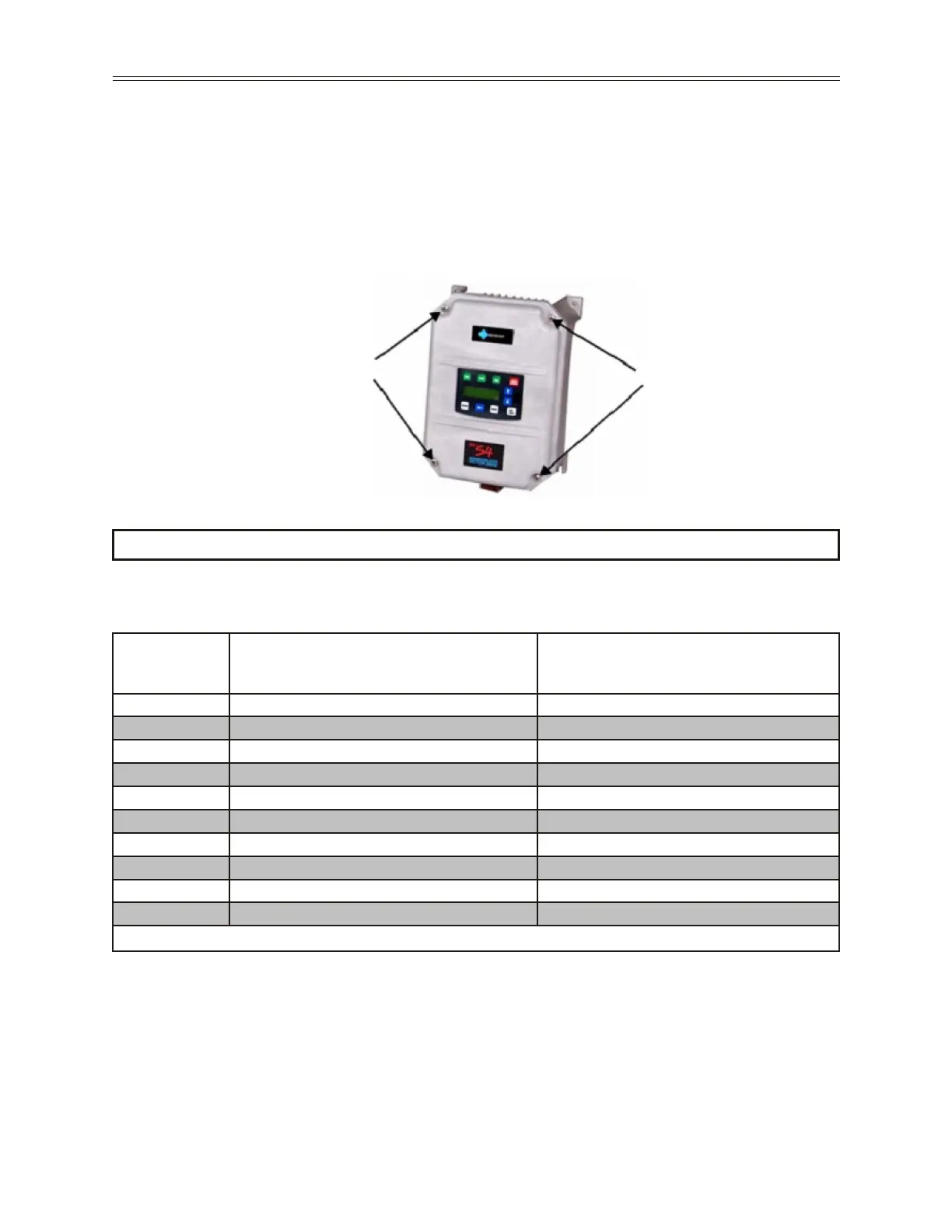
The arrows in Figure 8 show the location of the S4 cover screws. Torque specications for control
terminals and power terminals are listed on page 31 & 32.
z NOTE: Ensure that the ventilation openings are not obstructed.
z NOTE: Avoid using sealed connectors around rubber-coated cables to seal the drive. These do not
allow any air transfer and can create condensation around the display.
RSi S4
Model
Required Dissipation for Models Entirely
Inside an Enclosure at Rated Current, 3KHz
Carrier Frequency (Watts)
Required Dissipation when Fins are External
to the Enclosure (Watts)
RSi001S42W 48 14
RSi002S42W 71 17
RSi003S42W 92 16
RSi005S42W 132 20
RSi007S42W 177 23
RSi010S42W 263 67
RSi015S42W 362 68
RSi020S42W 550 97
RSi025S42W 653 96
RSi030S42W 779 103
Figure 8: Cover Assembly
3.6 Heat Dissipation
Heat Dissipation for Models Entirely Inside an Enclosure at 200 - 230VAC
 Loading...

