161
B - REMOTE COMMUNICATION
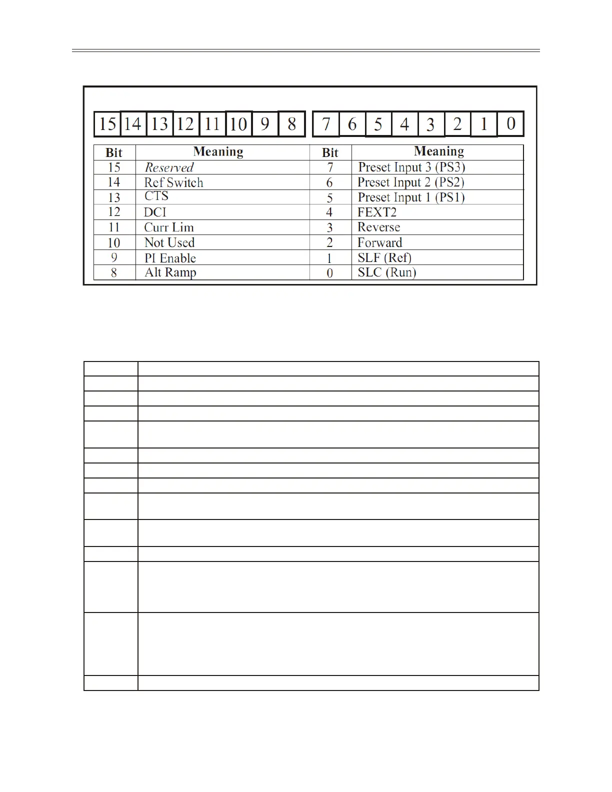
Figure 40: Control Word 1 (ModBUS Address 40904)
Ext Ref Freq 1 & 2 These parameters provide access for changing the frequency reference over the
serial link. Freq 2 is an alternate access for changing frequency.
Control Word 1 Bit Description
Bit Description
Bit 15 Reserved. This bit must be maintained at a logic ‘0’ for proper drive operation.
Bit 14 Ref Switch
Bit 13 CTS
Bit 12
The drive will start injecting DC current into the motor when set to a 1, and will stop when this
bit is cleared.
Bit 11 Curr Lim
Bit 10 Not Used
Bit 9 PI Enable
Bit 8
Ramp Select
0 - Main Ramp is selected. 1 - Alternate Ramp 1 is selected.
Bit 7-5
Preset Speed Selection. These bits work in the same manner as the PS1-3 digital inputs. Please
refer to I/O 20-26 for more information about the preset speed selection.
Bit 4 FEXT2
Bit 3-2
Start/Stop (bit 3, 2)
00 - Stop 01 - Forward
10 - Reverse 11 - Forward (Forward has priority)
Note: (Run/Stop Setting) must be set to “Serial” for these bits to have any effect.
Bit 1
Serial Speed Reference Select. If set to ‘0’ the frequency speed reference comes from External
Frequency Reference 1. If set to ‘1’ the frequency speed reference comes from External
Frequency Reference 2. Please refer to the end of this section for the description of these
registers.
Note: (Ref Source) and/or (Alt. Ref Src) must be set to “Serial” for this bit to have any effect.
Bit 0 Serial link Control (Run)
 Loading...

