Chapter 5 – Parameter List
5-2
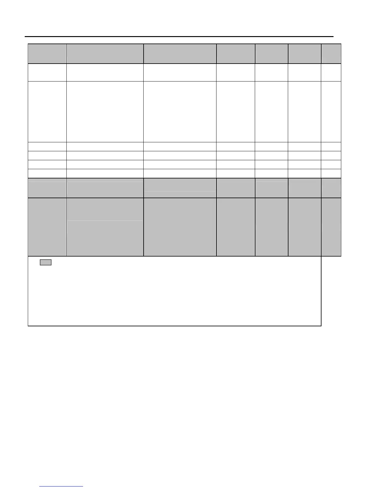
PARAM Description
LCD Keypad
Display Setting Range
Factory
Default
Adj.
During
Run Page
DRV-24 Output Current
Ia= 0A Ib= 0A
Ic= 0A It = 0A
View Only 6-7
DRV-26 Keypad Reference Mode
KeyRefMode
Minimum
Spd
Last Spd
Preset Spd 1
Stop
Fault
Disable
Disable Yes 6-7
DRV-27 Current, Phase U
Ia Current, 0.0A
View Only 6-7
DRV-28 Current, Phase V
Ib Current, 0.0A
View Only 6-7
DRV-29 Current, Phase W
Ic Current, 0.0A
View Only 6-7
DRV-30 Current, Ground
Ground Curr, 0.0A
View Only 6-7
DRV-91
(Note 6)
Drive Mode 2 (Run/Stop
Method)
Drive mode 2
Keypad
Fx/Rx-1
Fx//Rx-2
Fx/Rx-1
No 6-7
DRV-92
Frequency Mode 2 (Frequency
Setting Method)
Freq mode 2
Keypad-1
Keypad-2
V1
V1S
I
V1+I
Pulse
Int. 485
Ext. PID
Keypad-1 No 6-7
The gray-highlighted parameters are hidden parameters and will only appear when the related functions are set.
Note 1: To change display from Hz. To RPM, see DRV 17.
Note 2: When operating in PI Mode (APP02 set to “yes”), the Set point will be displayed when stopped. The units
of the set point are selected using I/O-86. When running, speed is displayed in Hz.
Note 3: Only displayed when APP-02 is set to “yes” (PI Mode).
Note 4: Only displayed when APP-80 is set to “yes” (Ext. Process PI Mode).
Note 5: DRV21 - 23 are only displayed when I/O 20 - 27 are set to “Speed-L, -M, -H”.
Note 6: DRV91, 92 are only displayed when I/O 20 - 27 is set to “LOC/REM”.

 Loading...