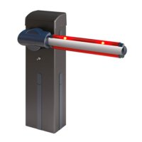
IANUS BT 300 KIT - IANUS BT 500 KIT - 43
D812457 10550_02
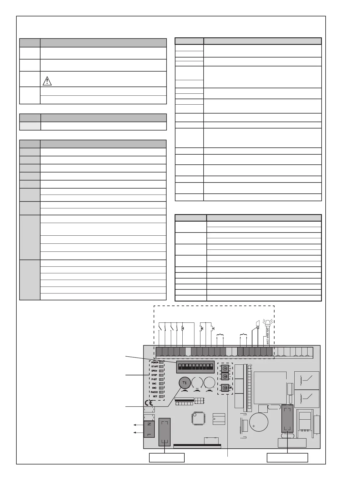
OPTIONAL FLASHING LIGHT
N
L
123456789101112131415161718192021222324252627
OPEN
COM
COM
STOP
PHOT 1
PHOT 2
FAULT PHOT 1
FAULT PHOT 2
NO
NC
NC
NO
NC
NO
ANT
START
NO
1 2 3 4
ON
5 6 7 8 9 10
F1
F2
F1: 800 mAT
F2: 3,15 AT
24V~ MAX 180mA
24VSafe~ MAX 180mA
SHIELD
WIRING DIAGRAM
*
3
*
1
*
2
*
4
*
*
KEYS Description
S1
Add Start Key
associates the desired key with the Start command�
S2
Add Pedestrian Key
associates the desired key with the pedestrian command�
S1+S2
>10s
Erase List
WARNING! Erases all memorized transmitters from the
receiver’s memory�
S3
Pressed BRIEFLY, it gives the START command�
HELD DOWN (>5 sec�), it activates the AUTOSET function�
*
1
TRIMMER
Description
T1 Waiting time before automatic closing
*
2
LEDS Description
POWER Steadily lit: - Mains power on - Board powered - Fuse F1 intact
START Lit: START input activated
OPEN Lit: OPEN pedestrian input activated
STOP Unlit: STOP input activated
PHOT Unlit: PHOT photocell input activated
SWC
Unlit: leaf fully closed
Lit: motor limit switch is disengaged
SWO
Unlit: leaf fully open
Lit: motor limit switch is disengaged
RADIO
(GREEN)
Unlit: remote programming not active
Radio LED only ashing: Remote programming active, waiting
for hidden key�
Flashing in sync with Set LED: Transmitter deletion in progress
Lit: remote programming active, waiting for desired key�
Lit 1s: Radio receiver channel activated
SET
Lit: Set key pressed / Autoset completed successfully
Flashes three times: Autoset in progress
Fast ashing 10s: Autoset failed
Flashing in sync with Radio LED: Transmitter deletion in progress
Lit 1s: Start/Stop after key S3 pressed
Lit 10s: Autoset completed correctly
*
3
Terminal
Description
L
Single-phase power supply 220-230V ~50/60 Hz
N
8
Flashing light 24V max� 25W
9
10
Antenna input�
Use an antenna tuned to 433MHz� Use RG58 coax cable to connect
the Antenna and Receiver� Metal bodies close to the antenna can
interfere with radio reception� If the transmitter’s range is limited,
move the antenna to a more suitable position�
11
12
Accessories power supply output�
13
16
Tested safety device power supply output (photocell transmitter
and safety edge transmitter)�
Output active only during operating cycle�
17
18
START command button (N�O�)�
Operation according to “3/4-STEP” logic
19
START and OPEN inputs common
20
OPEN command button (N�O�)�
Gate opened with this command� If the input stays closed, the
leaves stay open until the contact is opened�
When the contact is open, the automated device closes following
the TCA time, where activated�
21
STOP and PHOT inputs common
23
The command stops movement� (N�C�)
If not used, leave jumper inserted�
24
PHOTOCELL 1 input (N�C�)�
If not used, leave jumper inserted�
25 Test input for safety devices connected to PHOT1�
26
PHOTOCELL 2 input (N�C�)�
If not used, leave jumper inserted�
27 Test input for safety devices connected to PHOT2�
*
4
DIP-SWITCH
Description
1
ON: Switches photocell 1 testing on
OFF: Switches photocell 1 testing o
2
ON: Switches photocell 2 testing on
OFF: Switches photocell 2 testing o
3
ON: Activates automatic closing
OFF: Excludes automatic closing
4
ON: Motor installed on the left
OFF: Motor installed on the right
5 Not used
6 Not used
7 Not used
8 Not used
9 Not used
10 Not used