MKF / MKFT (E5) 06/2020 page 22/176
2.3 Lateral control panel
(1)
(4a)
(4b)
(5)
(7)
(9)
(3)
(5a)
(8)
(10)
(1)
(4a)
(4b)
(5)
(7)
(9)
(3)
(5a)
(8)
(10)
(11)
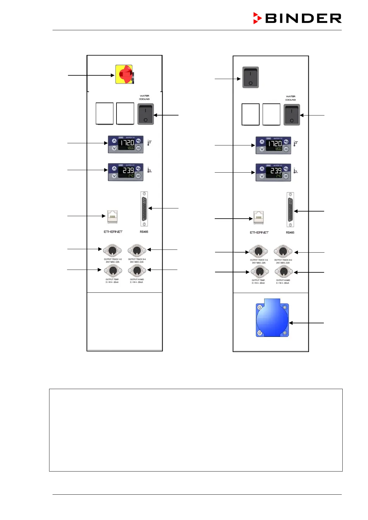
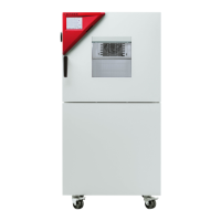
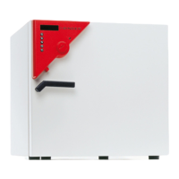
MKF 56 MKF / MKFT 115 / 240 / 720
Figure 5: Lateral control panel at the right side of the humidity module with options
(1) Main power switch ON/OFF
(2) not used
(3) Switch for water cooling (option, not com-
ing with size 720)
(4) Temperature safety device class 2 for
over and under temperature (option):
Entry displays for upper (4a) and lower
(4b) temperature limit
(5) Ethernet interface for computer commu-
nication
(5a) RS485 interface for computer communication
(option)
(6) not used
(7) 2 zero-voltage relay outputs via operation lines
(8) 2 zero-voltage relay outputs via operation lines
(9) Analog output for temperature (option)
(10) Analog output for humidity (option)
(11)
Socket 230 V AC, max. 500 W (MKF/MKFT 115,
240, 720)