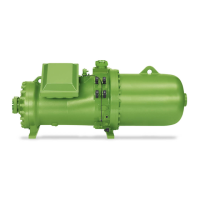
Клапан жидкостного впрыска
представляет собой специально
разработанный расширительный клапан,
предназначенный для осуществления
жидкостного впрыска. eгo пропускная
способность должна регулироваться на
основании значений температуры
нагнетания, установленной в пределах
100 .. 110°С (например, Danfoss TEAT20,
Alco 935-101-B, Sporlan Y1037).
Баллон этого клапана монтируется на
линию нагнетания:
• сделайте поверхность трубопровода
гладкой и зачистите её до яркого
металла, отступив от запорного вентиля
на нагнетании приблизительно 10 .. 20 см
.
• нанесите слой теплопередающей пасты
на место контакта.
• прочно закрепите баллон
расширительного клапана, используя
соответствующие фиксаторы.
Учитывайте тепловое расширение!
• Теплоизолируйте баллон, если
компрессор обдувается воздушным
потоком от конденсатора воздушного
охлаждения.
Расположение трубопроводов
Для обеспечения сплошного потока
жидкости (отсутствие пузырьков),
подаваемой через расширительный
клапан, он должен устанавливаться на
горизонтальном участке жидкостной
линии, которая сразу за клапаном
должна быть загнута вниз (см. рис.9).
Присоединение клапана жидкост-
ного впрыска к компрессору
•
минимум на 20 см выше места входа в
компрессор линии жидкостного впрыска
•
труба непосредственно стыкуется
через адаптер с выходным диаметром
16 мм – 5/8"
1 Серия № CSH65 361 332-02
2 Серия № CSH75 361 332-02
3 Серия № CSH85 361 332-03
Внимание!
Возможны разрушения от
вибрации!
Закрепляйте клапан жидкостного
впрыска и электромагнитные
клапана с помощью фиксаторов!
Следите за уровнем вибрации
при функционировании установки!
!
!
25
Kältemittel-Einspritzventil
Zur Kältemittel-Einspritzung eignen
sich nur spezielle Expansionsventile.
Sie müssen in Abhängigkeit von der
Druckgastemperatur regeln – Einstell-
Temperatur 100 .. 110°C (z. B.
Danfoss TEAT20, Alco Serie 935-
101-B, Sporlan Y1037).
Der Ventil-Fühler muss an der Druck-
gas-Leitung montiert werden:
• Rohr an der Kontaktfläche sorgfäl-
tig glätten und Oberfläche reinigen,
bis sie metallisch blank ist.
Entfernung zum Druckabsperr-
Ventil ca. 10 .. 20 cm
• Kontaktfläche mit Wärmeleitpaste
bestreichen.
• Fühler mit stabilen Rohrschellen
befestigen. Wärmedehnung beach-
ten!
• Fühler isolieren bei Aufstellung des
Verdichters im Luftstrom des Ver-
flüssigers.
Rohrführung
Um blasenfreie Flüssigkeits-Versor-
gung für das Einspritzventil zu ge-
währleisten, muss der Rohrabgang
von einem horizontalen Leitungsab-
schnitt aus zunächst nach unten
geführt werden (siehe Abb. 9).
Anordnung des Kältemittel-
Einspritzventils am Verdichter
• min. 20 cm über Kältemittel-
Einspritz-Anschluss
• Rohrverbindung direkt nach unten
Adapter-Ausgang 16 mm - 5/8"
Bausatz-Nr. CSH65: 361 332-02
Bausatz-Nr. CSH75: 361 332-02
Bausatz-Nr. CSH85: 361 332-03
Achtung!
Schwingungsbrüche möglich!
Kältemittel-Einspritz- und
Magnetventile mit Schelle
befestigen!
Schwingungsverhalten bei
Betrieb kontollieren!
!
!
Liquid injection valve
Specially designed expansion valves
are only suitable for liquid injection.
They must control according to the
discharge temperature with a setting
of 100 .. 110°C (e. g. Danfoss
TEAT20, Alco series 935-101-B,
Sporlan Y1037).
The valve bulb must be mounted on
the discharge line:
• Smoothen the tubes surface care-
fully and clean the surface to bright
metal. Distance from discharge
shut-off valve approx. 10 .. 20 cm
• Apply heat transfer paste to the
contact surface.
• Fix the bulb firmly with adequate
pipe clips. Mind heat expansion!
• Insulate the bulb if the compressor
is located in the condenser air
stream.
Pipe runs
To ensure a bubble free liquid supply
to the liquid injection valve, the con-
nection must be made on a horizontal
section of the liquid line and the pipe
should at first lead downwards (see
figure 9).
Fitting of the liquid injection valve
at the compressor
• min. 20 cm above liquid injection
connection
• line connection directly downwards
adaptor outlet diameter 16 mm - 5/8"
complete No. CSH65: 361 332-02
complete No. CSH75: 361 332-02
complete No. CSH85: 361 332-03
Attention!
Vibration fractures possible!
Fit liquid injection and solenoid
valves with clips!
Check vibration behaviour dur-
ing operation!
!
!
 Loading...