3. Power on the unit and verify that the outputs are turned off. The button
should not be illuminated.
4. From the MENU, navigate to COUP using the keys, keys or the rotary
knob.
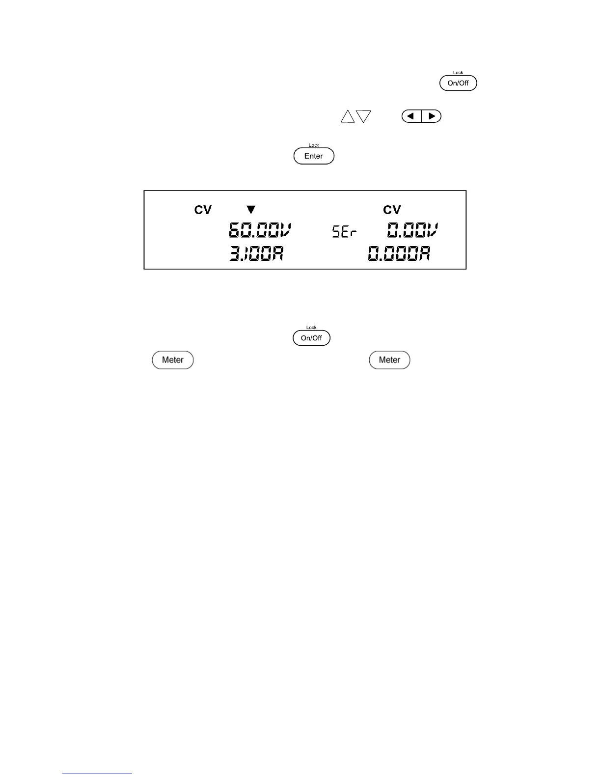
5. Select the option SEr and press the button. The power supply will
momentarily display SEr SUCC. The VDF will look like the figure below:
Figure 13 - Series Mode (CH1 + CH2)
6. Set the voltage and current for CH1 & CH2.
7. Enable the outputs by pressing the button, which will illuminate.
8. If the button is not illuminated, press the button once to display
the measured voltage and current at the output.
Parallel Mode (PAr)
Parallel mode will increase the available current range that can be supplied to 6 A (max) by
adding the output current of channels 1&2. The maximum output current in Parallel mode
becomes 6.0 A and a total of 30 V. The default voltage and current settings in Parallel mode are
6.0A and 0.0 V.
Follow the steps below to enable this feature.
1. Power off the unit and remove all wiring from the output terminals.
2. Refer to the below illustration to make the parallel connections.
www.GlobalTestSupply.com
Find Quality Products Online at: sales@GlobalTestSupply.com