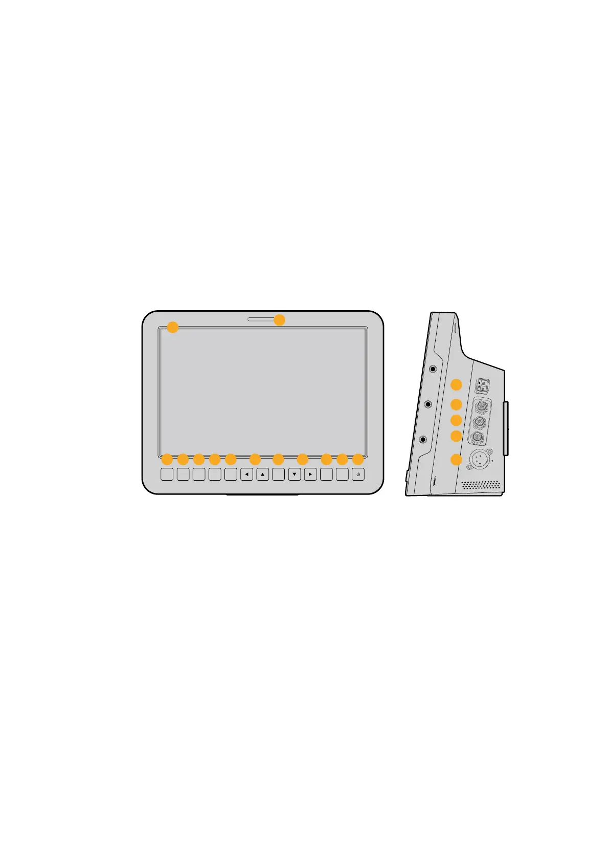
Right Panel
6 Optical Input/Output
Optical input and output allows cable runs of up to 28 miles when the optional SFP
optical module is fitted.
7 SDI Out
SDI output for connecting to a switcher or other device.
8 SDI In
SDI input allows the camera operator to view the Program (PGM) output.
9 Reference Input
Allows multiple cameras to be genlocked to a blackburst or tri-level reference signal.
10 Power
12 – 24V power input for power supply and battery charging, where applicable.
Refer to the ‘Blackmagic Studio Camera - right panel’ section in this manual for
more details.
Rear Panel
11 10” LCD
Monitor live camera output or program output, or view the menu. See the ‘monitoring
settings’ in this manual for more details.
12 Rear Tally Light
When lit, it indicates to the camera operator that their camera is currently live.
13 Focus Button
Press once to auto focus or twice to display focus peaking on the LCD.
14 Iris Button
Press once for auto exposure.
15 Push To Talk Button PTT
Press and HOLD to talk. Press twice in quick succession for hands free communication.
Press again to revert to the default behavior.
16 Program PGM Button
Press to toggle between live camera output and program output from a switcher
control room.
17 Look Up Table LUT Button
Currently not implemented.
SDI OUT
OPTICAL OUT
OPTICAL IN
SDI IN
REF
12V
IRIS PTT PGM LUT SET DISPLAY MENU
FOCUS
SDI OUT
OPTICA
L OUT
OPTICAL IN
SDI IN
REF
12V
IRIS PTT PGM LUT SET DISPLAY MENU
6
7
8
9
10
11
12
13 14
15
2016 21
17
221918 18
1010Camera Features