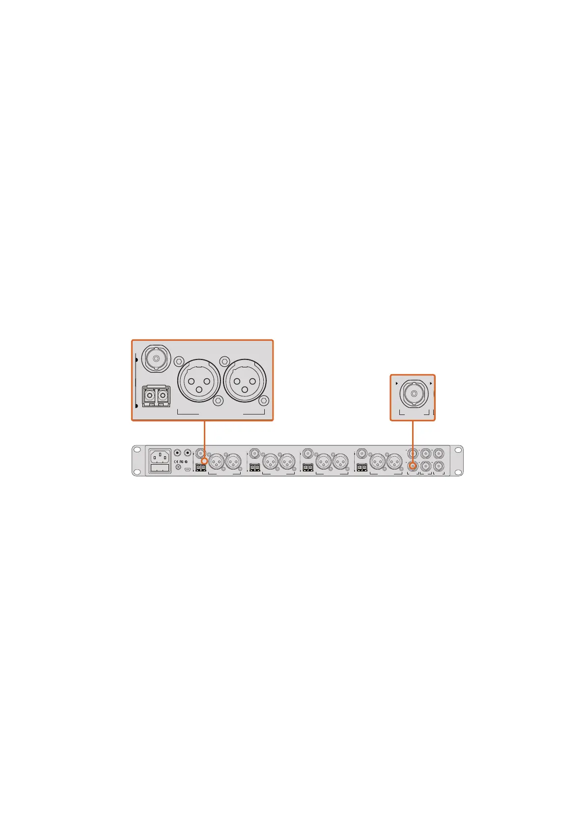
Connecting via Optical Fiber
1 With the user upgradable optical fiber SFP module installed in your Studio Camera,
connect the Optical Out/In to the Optical Out/In on an ATEM Studio Converter.
2 Connect a suitable SDI out from ATEM Studio Converter to any SDI In on the
ATEM switcher.
3 Connect any one of the ATEM switcher’s SDI outputs, except down converted or multi
view outputs to ATEM Studio Converter’s SDI In. Camera control signals are not sent via
the multi view and down converted SDI outputs.
4 On your Blackmagic Studio Camera, press Menu. Navigate to Studio Settings>Camera
Number and set it to match the switcher input. For example, if studio camera 1 is
connected to Cam 1 on the ATEM switcher, your camera number must also be set to 1.
This ensures tally is sent to the correct camera.
Open ATEM Software Control Preferences and set the switcher’s button mapping to make sure
you are switching the right camera with correct tally. Now you have a video connection from the
switcher to your Blackmagic Studio Camera, you can also get the advantage of live tally
indicators on your camera, as well as being able to view the program feed of the switcher by
pressing your camera’s PGM button.
Connect multiple Blackmagic Studio Cameras via optical fiber using an ATEM Studio Converter.
Using Camera Control
Launch ATEM Software Control and click on the Camera button located at the bottom of the
software window. You’ll see a row of labeled camera controllers containing tools to adjust and
refine each camera’s image. The controllers are easy to use. Simply click the buttons using your
mouse, or click and drag to adjust.
Camera Control Selection
The button row at the top of the camera control page lets you select the camera number you
would like to control. If you have more cameras that fit onto the window size, or you are running
the color corrector window, then you can use these buttons to select between which camera
you would like to control. If you are using an Aux output for monitoring your camera control,
pushing these buttons to change the camera to control will also send that camera’s video
output to the Aux output. Your chosen Aux output for camera control can be set in the general
switcher settings.
4321
OPTICAL OUT/IN
SDI OUT
L R
RL
USB 2.0
+12V BACKUP
POWER
OPTICAL OUT/IN
SDI OUT
L R
ANALOG AUDIO OUT OPTICAL OUT/IN
SDI OUT
L R
ANALOG AUDIO OUT OPTICAL OUT/IN
SDI OUT
L
OUT
R
ANALOG AUDIO OUTANALOG AUDIO OUT
IN
PGM SDI
OUT
IN
MIC
OUT
IN
H/PHONE
AES/EBU TALKBACK LOOPS
4321
OPTICAL OUT/IN
SDI OUT
L R
RL
USB 2.0
+12V BACKUP
POWER
OPTICAL OUT/IN
SDI OUT
L R
ANALOG AUDIO OUT OPTICAL OUT/IN
SDI OUT
L R
ANALOG AUDIO OUT OPTICAL OUT/IN
SDI OUT
L
OUT
R
ANALOG AUDIO OUTANALOG AUDIO OUT
IN
PGM SDI
OUT
IN
MIC
OUT
IN
H/PHONE
AES/EBU TALKBACK LOOPS
4321
OPTICAL OUT/IN
SDI OUT
L R
RL
USB 2.0
+12V BACKUP
POWER
OPTICAL OUT/IN
SDI OUT
L R
ANALOG AUDIO OUT OPTICAL OUT/IN
SDI OUT
L R
ANALOG AUDIO OUT OPTICAL OUT/IN
SDI OUT
L
OUT
R
ANALOG AUDIO OUTANALOG AUDIO OUT
IN
PGM SDI
OUT
IN
MIC
OUT
IN
H/PHONE
AES/EBU TALKBACK LOOPS
3333Using ATEM Software Control