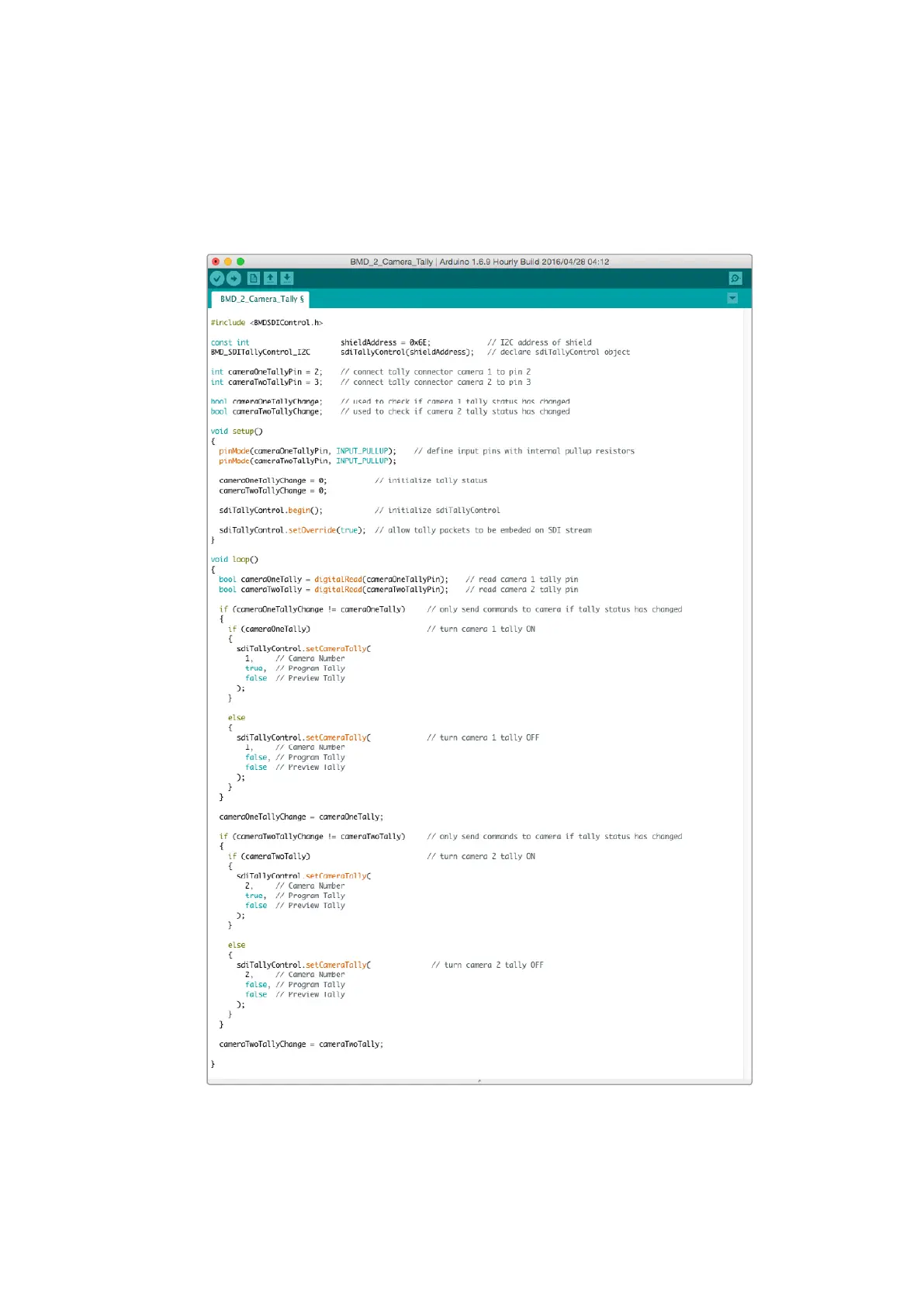
The example sketch below shows how the Blackmagic Arduino shield is programmed to send a
tally signal to the camera that has been switched to the program output. All SDI switchers that
have open collector outputs are configurable for tally using the Blackmagic 3G-SDI Arduino
Shield. For more information, download the Blackmagic 3G-SDI Arduino Shield instruction
manual from the Blackmagic Design support center at www.blackmagicdesign.com/support.
The example sketch above shows how the Blackmagic Arduino shield is programmed to detect
a tally signal for input 1 or 2 via the switcher’s tally output, and then embed that tally signal into
the shield’s SDI output. The tally light on the corresponding camera will then illuminate.
2929Connecting Tally using the Blackmagic 3G-SDI Arduino Shield