66
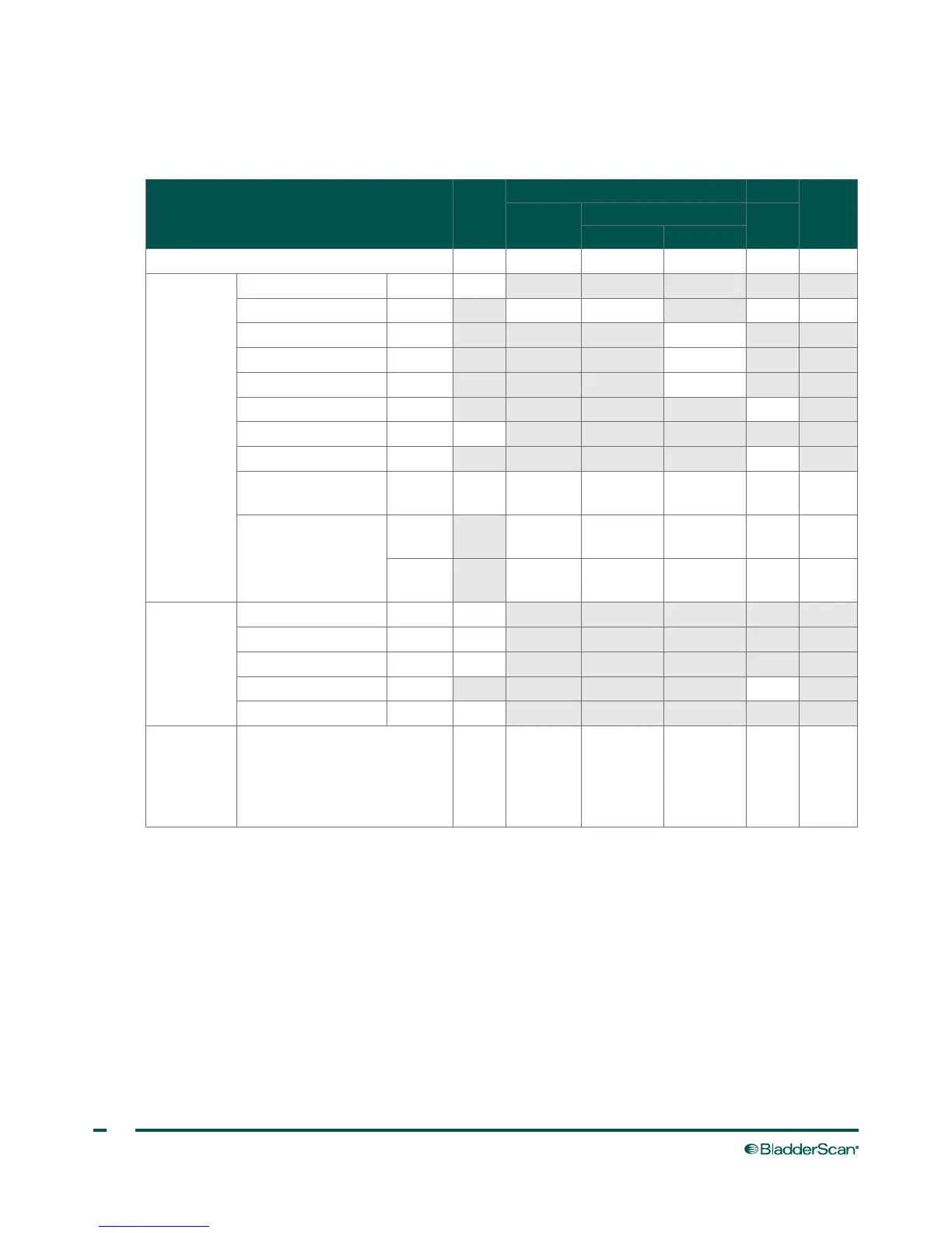
Table 23. Ultrasound Acoustic Output Parameters (IEC Standard)
Values in this table are the maximum readings obtained from three test results.
INDEX LABEL MI
TIS TIB
TIC
SCAN
NON‑SCAN
NON‑
SCAN
AAPRT
≤1 cm² AAPRT
>1 cm²
Maximum index value 0.460 2.84E‑3 — — — *
Associated
Acoustic
Parameter
pr.a (MPa) 0.607
P (mW) 1.28 — — †
min of [Pα(zs), Ita, α(zs)] (mW) —
zs (cm) —
zbp (cm) —
zb (cm) —
z at max. Ipi,α (cm) 1.90
deq(zb) (cm) —
fawf (MHz) 1.74
1.74,
2.57 §
— — — †
Dim of Aaprt
X (cm)
1.12,
1.10 §
— — — †
Y (cm)
1.12,
1.10 §
— — — †
Other
Information
td (μsec) 2.89
prr (Hz) 400
pr at max. Ipi (MPa) 0.680
deq at max. Ipi (cm) —
Ipa.3 at max. MI (W/cm²) 8.64
Operating
Control
Conditions
Each scan point along the scan
line consists of two transmit
pulses. The first pulse is 1 cycle
at 2.95 MHz and the second
pulse is 5 cycles at 1.74 MHz
* Intended use does not include cephalic uses, so TIC is not computed.
§ Data for each pulse is provided and seporated by a comma.
† No data reported.
Notes:
1. Information need not be provided for any formulation of TIS not yielding the maximum value of TIS for that mode.
2. Information need not be provided regarding TIC for any transducer assembly not intended for transcranial or neonatal cephalic uses.
3. Information on MI and TI need not be provided if the equipment meets both the exemption clauses given in 51.2 aa) and 51.2 dd).
4. Scanning: Each frame of the overall 3D scan consists of scanning a sector and then rotating the sector plane about the center axis of the
scan through a full 360°. The maximum intensity values calculated only occur at the center of the rotation where the planes overlap.