9
Installation
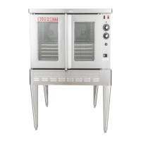
Oven Assembly
Top Oven
Electric Cord
Bottom Oven
Electric Cord
Utility
Box
Retainer
Bracket
Figure 8
7. Reattach the right side panels once the electrical con-
nections are complete.
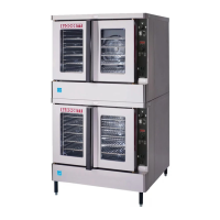
Water and Drain
1. Attach the water manifold to the back of the ovens.
2. Attach the short water hose from the water manifold
to the utility box underneath the oven.
Utility
Box
Short
Hose
Water Manifold
Figure 9
3. Attach the supplied elbow assembly to the oven drain
outlet on both units.
4. Attach the supplied drain hose to the top unit.
5. Cut for proper length into the funnel drain. Use the
remaining piece of hose for the bottom oven if neces-
sary. See Figure 6 for location of drain connection on
back of ovens.
Cavity Vent Extension
1. Attach the cavity vent extension using the silicon tub-
ing and two clamps provided.
2. Remove the existing screw and use it to secure the
top section in the bracket. The tabs on the bracket will
deect for a secure t.
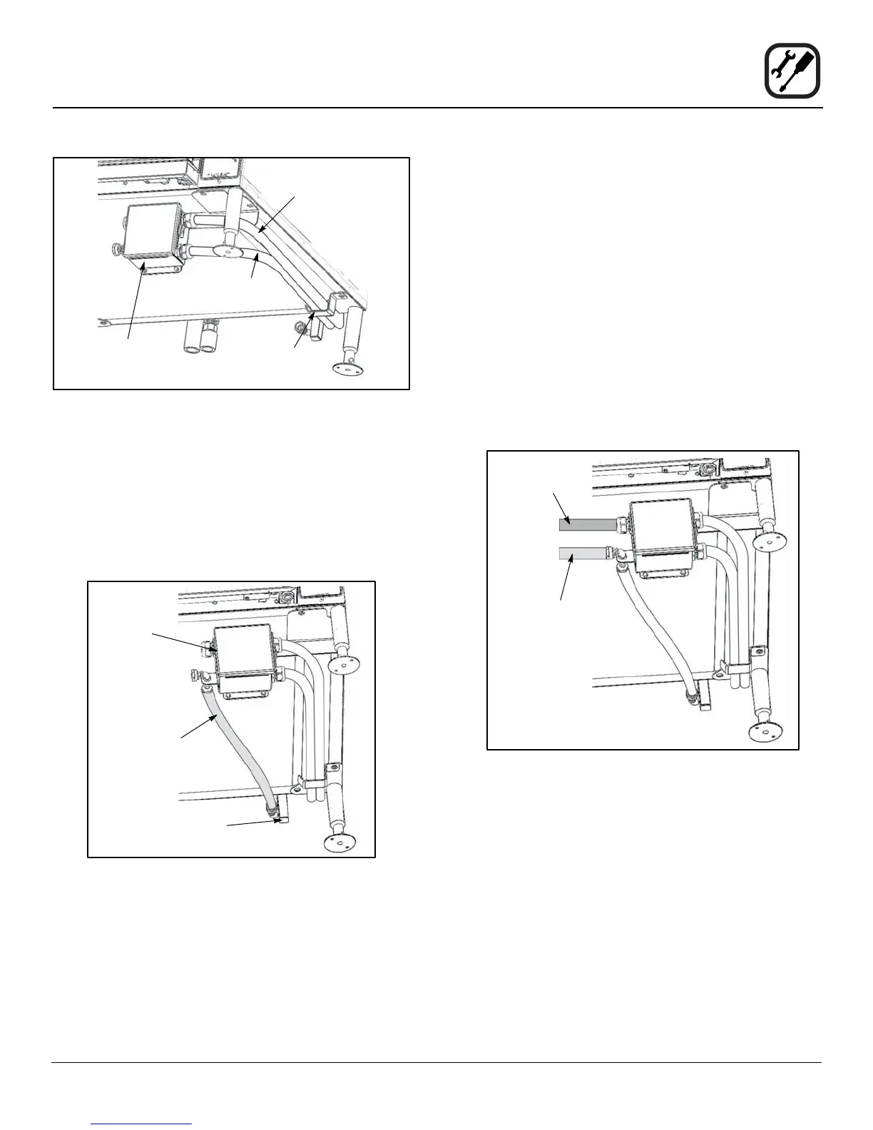
Utility Supply Connection
1. Connect incoming power from the ship to the electri-
cal connection on the utility box underneath the oven.
See Figure 10.
2. Connect the cold water supply from the ship to the
incoming water connection on the utility box under-
neath the oven. A 10’ water hose is supplied for your
convenience. See Figure 10.
Incoming
Electrical
Supply
Incoming
Water
Supply
Figure 10
 Loading...