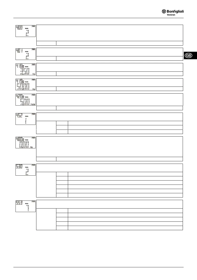
Switching Frequency 400 - The factory setting of the switching frequency is dependent on the
configuration (configuration 110: 2 kHz, configuration 410: 4 kHz). Higher switching frequencies
reduce the noise of the motor but require a reduction of the output current (see technical data in
the operating instructions manual).
Setting: 2 kHz, 4 kHz, 8 kHz, 12 kHz, 16 kHz
Min. Switching Frequency 401 – defines the minimum value the switching frequency is reduced
automatically in the case of a thermal overload of the frequency inverter.
Setting: 2 kHz, 4 kHz, 8 kHz, 12 kHz, 16 kHz
Minimum Frequency 418 - the start command entered via the control unit or digital inputs
S2IND, S3IND results in an acceleration of the drive to the minimum frequency.
Setting: 0.00 Hz ... 999.99 Hz
Maximum Frequency 419 - The speed range of the drive is limited by the maximum output fre-
quency of the frequency inverter.
Setting: 0.00 Hz ... 999.99 Hz
Acceleration (Clockwise) 420, Deceleration (Clockwise) 421 - the ramps define how fast the
output frequency is changed after a start, stop or brake command or when the reference value is
changed.
Setting: 0.00 Hz/s ... 9999.99 Hz/s
Operation Mode 452 (for multi-function input); the set point at input MFI1 can be adjusted ac-
cording to the connected signal source.
1 - voltage signal, 0 V ... 10 V (factory setting)
2 - current signal, 0 mA ... 20 mA
Setting:
3 - digital fixed frequency change-over, 0 V ... 24 V, digital input
Fixed Frequency 1 480, Fixed Frequency 2 481 - change-over between the two fixed frequen-
cies is effected via the fixed frequency change over function of the multi-function input MFI1.
Operation Mode 452 (multi-function input on setting 3). Via the data set change-over S4IND,
S5IND, the fixed frequency in one of the four data sets can be selected.
Up to 8 fixed frequencies can be parameterized and selected via the control of the digital inputs.
Setting: -999.99 Hz ... 999.99 Hz
Op. Mode Digital Output 1 530, Op. Mode Digital Output 3 532 - various control and monitoring
functions can be assigned to the digital output S1OUT and the relay output S3OUT.
0 - switched off
2 - run signal, drive turning/not turning message
3 - fault message
11 - Warning
41 - trigger electro-mechanical brake
Setting:
1xx - inverted operation mode (LOW active)
Analog Operation 553 - output MFO1 supplies a pulse width modulated signal (0 V ... 10 V)
which is proportional to an actual value.
7 -
actual frequency, 0 Hz ...
Maximum Frequency 419
20 - active current, 0 A ... I
FIN
30 -
active power P
wirk
, 0 kW ... Rated Mech. Power 376
50 - effective current, 0 A ... I
FIN
Setting:
52 - machine voltage, 0 V ... 1000 V
09/08 41
 Loading...


