3 Electrical Installation
Danger!
• When the frequency inverter is disconnected from power supply, the mains, DC-link voltage and
motor terminals may still be live for some time. Wait for some minutes until the DC link capaci-
tors have discharged before starting to work at the unit.
• The unit may only be connected with the power supply switched off.
• Make sure that the frequency inverter is discharged.
3.1 EMC Information
The frequency inverters are designed for operation in industrial applications. Electromagnetic interference can be
avoided by the following precautions:
• Install the frequency inverters and commutating chokes on a metal mounting panel. Ideally, the mounting
panel should be galvanized.
• Provide proper equipotential bonding within the system or the plant. Plant components such as control cabi-
nets, control panels, machine frames, etc. must be connected by means of PE cables.
• Connect the frequency inverter, the commutating choke, external filters and other components to an earthing
point via short cables.
• Keep the cables as short as possible and avoid sagging cables for installation.
• Contactors, relays and solenoids in the electrical cabinet are to be provided with suitable interference suppres-
sion components.
• The mains connection cable must be installed separate from the control, data and motor cables.
• Connect the shield of the motor cable to ground potential properly on both sides by using shield clamps.
• Connect the shield of the control cables to ground potential properly on both sides.
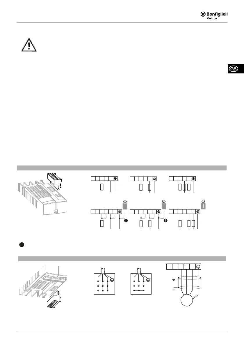
3.2 ACTIVE Cube 201 (up to 3.0 kW) and 401 (up to 4.0 kW)
Mains power connection, X1
X1
1ph / 230V AC
+
-
L1
L2
L3
L1
N
PE
3ph / 230V AC
3ph / 400V AC
+
-
L1
L2
L3
L1
L2
L3
PE
2ph / 230V AC
+
-
L1
L2
PE
L2 L3
L1
250 W … 1.1 kW
2ph / 230V AC1ph / 230V AC
1.5 kW … 3.0 kW
L1 N PE
+
-
L1
L2
L3
L1
3ph / 230V AC
3ph / 400V AC
PE
1.5 kW … 3.0 kW 1.5 kW … 4.0 kW
+
-
L1
L2
L3
L1
L1
L2
PE
L1
+
-
L1
L2
L3
L1
L2
L3
1
With a mains current above 10 A, the mains power connection 230 V 1ph/N/PE and the mains power connec-
tion 230 V 2ph/N/PE are to be done on two terminals.
Motor power connection, X2
X2
Star connection
V
W
U
Delta connection
V
W
U
V
W
U
Rb2
Rb1
M
3~
Use the terminals R
b1
and R
b2
to connect a brake resistor.
09/08 31

 Loading...


