+
12V
AMAX 3000 BE / 4000
Y
R
Y
G
B
AMAX 2100 / 3000
DX3010
R
B
G
DX3010
R
B
G
Y
R
B
G
Y
_
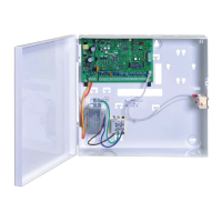
Figure 4.6: Connecting DX3010 to the AMAX Panel
Status Indicator
None.
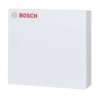
B426
General
AMAX panel supports up to two communication modules:
– ITS-DX4020-G and B426 or
– B426 and B426
The B426 Ethernet communication module supports monitored two-way IP communication via
Ethernet to perform alarm transmission, remote programming, and control of the AMAX panel.
Installation
1. Disconnect all power supplies of the AMAX panel before installing B426.
2. Use the standard three-hole installation mode to install B426 in the enclosure of the
AMAX panel or another enclosure. For more information refer to Module Installation, page
26 and to B426 Ethernet Communication Module.
3. Use network or direct connection to access the built-in web server when reconfiguring
the module or when connecting the module to the AMAX panel with RPS.
Address Setting
Set the rotary switch to 6 which corresponds to option bus address 134 for the first B426.
Set the rotary switch to 9 which corresponds to option bus address 250 for the second B426.
Wiring
The following graphic shows how to wire B426 to the option bus 1 or 2 of the AMAX panel.
Make sure, that the cable doesn’t exceed 150 meters.
4.4.4
4.5
4.5.1
4.5.2
4.5.3
AMAX panel Optional Modules and Peripheral Devices | en 19
Bosch Sicherheitssysteme GmbH Installation Manual 2015.05 | 06 | F.01U.309.277

 Loading...