2. Use the standard three-hole installation mode to install B450 in the enclosure of the
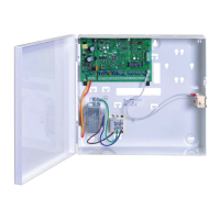
AMAX panel or another enclosure. For more information refer to Module Installation, page
26 and to B450 Conettix Plug-in Communicator Interface.
3. Instert SIM card into B442.
4. Insert B442 into B50.
P B442 clicks and the module combination is ready to be wired.
Address Setting
Set the rotary switch to 6 which corresponds to option bus address 134.
Wiring
The following graphic shows how to wire B450 to the option bus of the AMAX panel.
AMAX 3000 BE / 4000
Y
R
Y
G
B
AMAX 2100 / 3000
R
B
G
B450
R
/
PWR
B / COM
G / B
Y / A
Figure 4.8: Wiring of B450 with an AMAX panel
Status Indicator
B450 with B442 or B443 provide several LED indicators. The following table describes the
heartbeat LED indicator of B450 and the status LED indicator of B442 or B443 (blue).
LED Condition Denotation
Heartbeat LED of B450 On Trouble Condition
Stable flash Normal Operation
3 quick flashes Communication error
Off Power failure or other failure conditions
Status LED of B442 or
B443
Stable flash Normal Operation
3 quick flashes Communication error
Off Power failure or other failure conditions
Table 4.11: B450 with B442 System Status Indicator
4.6.2
4.6.3
4.6.4
AMAX panel Optional Modules and Peripheral Devices | en 21
Bosch Sicherheitssysteme GmbH Installation Manual 2015.05 | 06 | F.01U.309.277
 Loading...
