DX4010V2
General
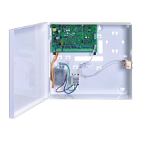
The DX4010V2 USB / serial interface module creates a local connection between the AMAX
panel and a serial printer (or a parallel printer with a converter box).
The recommended printer is STAR MICRONICS SP500 SP512MD42.
The printer can be connected to the DX4010V2 via a serial cable.
Installation
1. Disconnect all power supplies of the AMAX panel.
2. Remove the screws from the enclosure cover to access the DX4010V2 board.
3. Connect the circuit wiring and install the jumper pins.
4. Replace the enclosure cover.
5. Connect a USB or serial cable to the printer.
6. Enable the print function in the user menu.
Address Setting
The option bus address is 253.
Figure 4.9: DX4010V2 DIP switch settings
Wirinig
The following graphic shows how to wire a DX4010V2 USB / serial interface module to the
option bus of the AMAX panel.
AMAX 3000 BE / 4000
Y
R
Y
G
B
AMAX 2100 / 3000
R
B
G
DX4010V2
R
B
G
Y
Figure 4.10: Wiring of DX4010V2
Status Indicator
None.
DX4020-G
General
The Conettix ITS-DX4020-G GPRS communication module allows IP communication via
commercial GPRS network. Transmission of alarm information via GPRS is the default for ITS-
DX4020-G. SMS or USB mode can be chosen for configuration. Remote programming and
control of the AMAX panel is supported.
4.7
4.7.1
4.7.2
4.7.3
4.7.4
4.8
4.8.1
22 en | Optional Modules and Peripheral Devices AMAX panel
2015.05 | 06 | F.01U.309.277 Installation Manual Bosch Sicherheitssysteme GmbH

 Loading...