Unit Installation
NOTICE
All field-installed wiring must comply with the National
Electric Code as well as all applicable local codes.
NOTICE
Properly-sized fusible safety switches or HACR circuit
breakers must be installed for branch circuit protection. See
the unit nameplate for maximum fuse or breaker size.
NOTICE
Operation of unit on improper line voltage or with excessive
phase imbalance will be hazardous to the unit, constitutes
abuse and may void the warranty.
NOTICE
All high-voltage connections must be torqued as specified by
the component’s manufacturer.
Refer to the unit’s electrical data on the unit’s nameplate for wire
and branch circuit protection sizing. Supply power voltage and
phasing must match the required voltage and phasing shown on
the unit’s nameplate. Operating the unit below the minimum
voltage, above the maximum voltage, or with incorrect phasing
can result in poor system performance or damage to the heat
pump. All field wiring must be installed by qualified and trained
personnel. Refer to the unit’s wiring diagram for field connection
requirements.
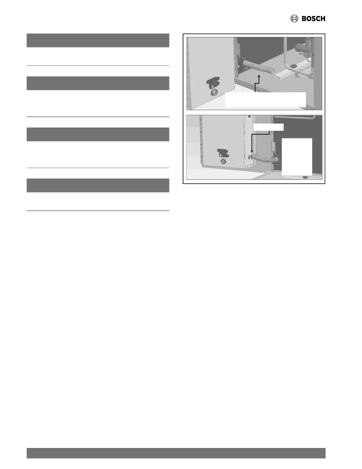
The Electrical Box is designed to swing out of the way allowing for
improved
access and servicing of the unit. To ensure proper
swing functionality, it is essential to provide sufficient wire
length. This can be achieved by using flexible conduit installed in
the unit (See Fig. 13) to guide the wire length determination.
Adequate wire length is required to enable full extension or
opening
of the control box, up to 90 degrees.
Fig. 13 Flexible Conduit
Wire Clamp
Secure
Flexible
Conduit
During Field
Installation
Strain-Relieving Flexible Conduit
as Shipped from the Factory
5.10.2 Power Supply and Ground Connections
To minimize the transmission of vibration from the unit cabinet to
the build
ing, enclose the power wiring to the heat pump in a
flexible conduit.
The unit is provided with concentric knockouts for attaching
common tr
ade sizes of conduit. Route the power-supply wiring
through the knockout opening and the flexible conduit inside the
unit. After the field wiring is routed to the electrical box, ensure
the wire clamp is tightened to secure the flexible conduit to the
electrical box. (See Fig. 13.) Always connect the ground lead
to the grounding lug provided in the unit. Follow the unit’s wiring
diagram
and the following instructions for power leads and
ground connection depending on unit options.
5.10.2.1 Standard Units
For standard models, power is connected to the line (L) side of
the comp
ressor contactor and the ground to the ground lug in the
unit electrical box.
5.10.2.2 Units with Disconnect Switch
For models with unit-mounted disconnect switches, connect the
field po
wer to the marked terminals on the disconnect switch,
and the ground to the ground lug or terminal block (in the case of
460V with a constant airflow motor) in the disconnect switch
box.
5.10.2.3 Units with Dual Power Supplies
For models with dual power supplies, one power supply feeds the
compres
sor, and a second power supply feeds the unit fan motor
and control circuit. The compressor power supply must be
connected to the line (L) side of the compressor contactor. The
2
0 |
CF Series Heat Pumps — 8733846299 (2024/11)





 To Next Page