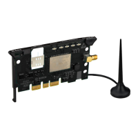
Hardware
2--9
1070 072 196-101 (00.06) GB
2.5.2 Protocol-Specific Settings
Protocol-specific settings for channel 0 are to be located at DIP switch S3
and S6. At DIP switch S6, only the switches 1 and 2 are assigned to channel
0.
The DIP switches S4, S5, and S6 with switch 3 and 8 are reserved for future
extensions, and must always be switched to OFF.
2.5.3 Protocol-Specific Settings V.24/20 mA
In general, 8 information bits and 1 stop bit are transferred.
S3
1 2 3 4 5 6 7 8 Function
off Control signals are not
scanned
on Control signals are scanned
off off off 38400 baud
on off off 57600 baud
off on off 600 baud / 10400 baud for
BUEP03E with switch S6-2 on
on on off 1200 baud
off off on 2400 baud
on off on 4800 baud
off on on 9600 baud
on on on 19200 baud
off No parity
on Parity active
off Odd parity
on Even parity
off off No protocol (tracer/monitor)
on off BUEP19E
off on BUEP03E
on on BUEP64
. For further information regarding BUEP03E, BUEP19E, and BUEP64,
please refer to the manual: R500 Computer Interface Module; order
no. 1070 072 131.

 Loading...
