Hardware
2--2
1070 072 196-101 (00.06) GB
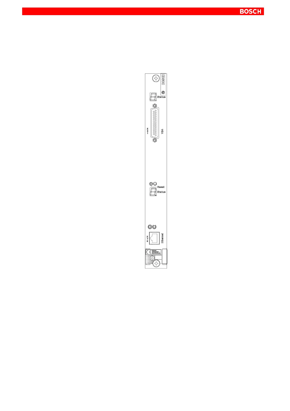
2.1 Front Panel
Link
Transmit
Receive
Status display
Channel 0
25-pin socket
Reset button
Link-LED
Receive-LED
Transmit-LED
10Base-T
Labeling field
Version identification
Status display
Channel 1
V.24/20 mA
Channel 0
Ethernet socket
Channel 1
Status Display
Each of the two channels on the COM-E is provided with a status display.
D For channel 0, the upper 7-segment display is responsible.
D For channel 1, the lower 7-segment display is responsible.
Interfaces
D The X31 interface is a V.24/20 mA interface. It is used for point to point
coupling to an external device or as a diagnosis/protocol monitor for the
Ethernet interface, compare with Tracer for PROFIBUS-FMS.
D The 10Base-T connector is used for the connection to the Ethernet net-
work.