Operation of the control unit
Control 8313 – 6720859567 (2017/03)
12
6.2 Function buttons and system status
Function buttons
The function buttons enable
• Manual operation
• Flue gas test
• Reset (e.g. high limit safety cut-out, SAFe)
System status, function status, component status
The status of the system, the functions and system components is
displayed via the Function status display ( Fig. 6, [1], page 12), the
System components status display ( Fig. 6, [15], page 12) and the
LED status display ( Fig. 5, [7]):
• Green = system in automatic mode
• Yellow = system in manual mode, Flue gas test, Service display or
Blocking fault SAFe
• Yellow flashing = Control unit coupling
• Red = Fault
6.3 Operating and display elements of the touch screen
Whether menu items can be displayed or selected depends on which
modules are inserted and which settings have been made.
The displays shown are examples. The display of the symbols depends
which software is installed, which modules are inserted and which
settings have been made.
The operating instructions contain information on operation of the
control unit.
▶ Observe operating instructions of the control unit and the heat
source.
The following displays can be called up via the touch screen:
• Heat source in the system
• Heat consumers and heat distributors in the system
• Monitor data
• Setting parameters for commissioning and system optimisation.
These parameters are protected by a code.
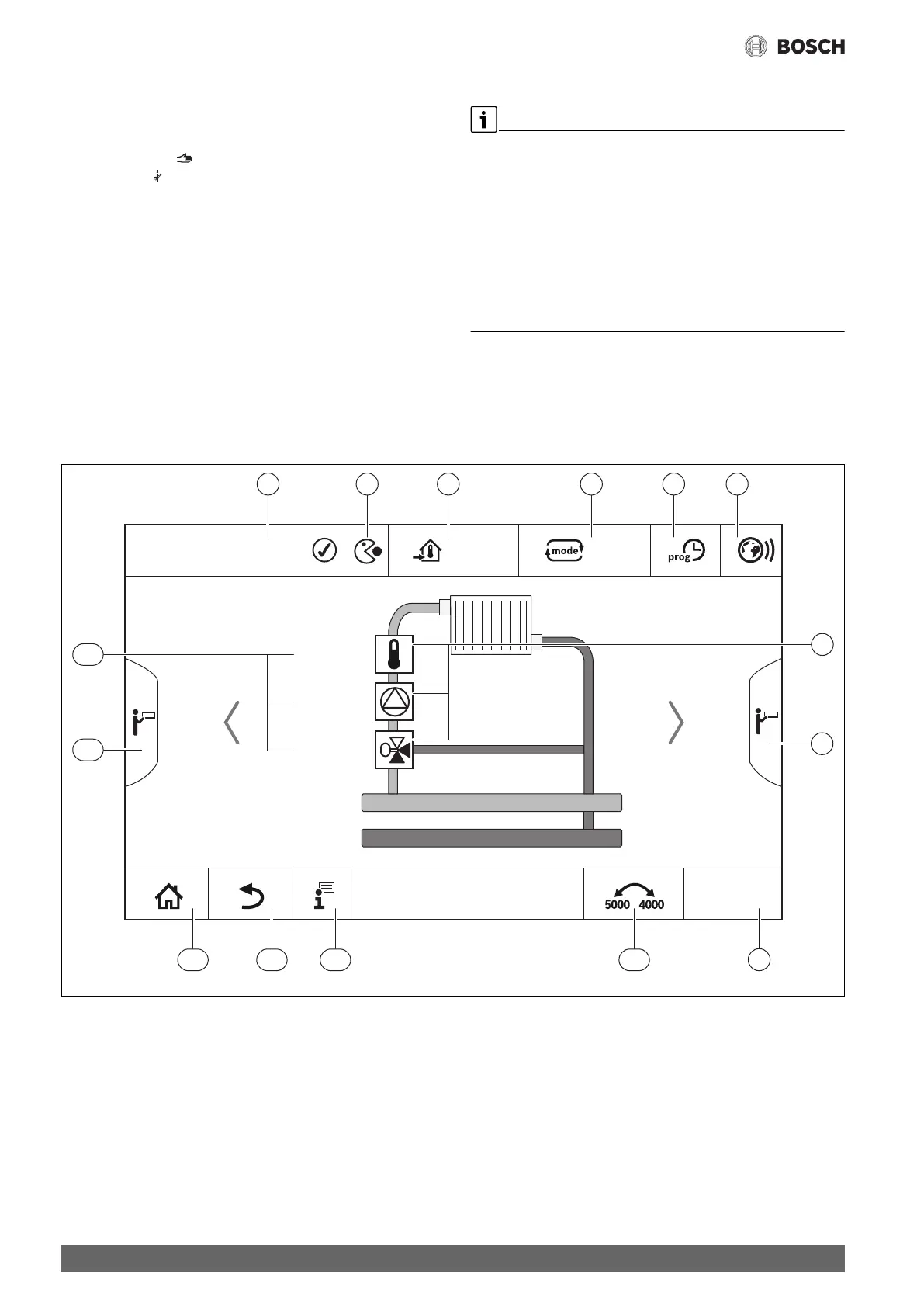
Fig. 6 Operating and display elements
[1] Display of system, subsystem or function
[2] Status display of active menu level
[3] Display of temperature set (set temperature)
[4] Display of operating mode set
[5] Display of time program set
[6] Display of Internet connection
[7] Display of system components
[8] Advanced functions for heating circuit, DHW
[9] Display of time
[10] Press field to switch between display types on the display
[11] Information menu
[12] Press field to go back to the previous level/screen
[13] Press field to return to the system overview
[14] Advanced functions of the heat source
[15] Status display of system components
The symbols used are listed in Chapter 23.3 on page 51,
accompanied by an explanation.
rese
12:00
50 °C
on/o
30 %
1 2 3 4 5 6
9
7
8
10111213
14
15
0010005510-001