Menu structure
19
Control 8313 – 6720859567 (2017/03)
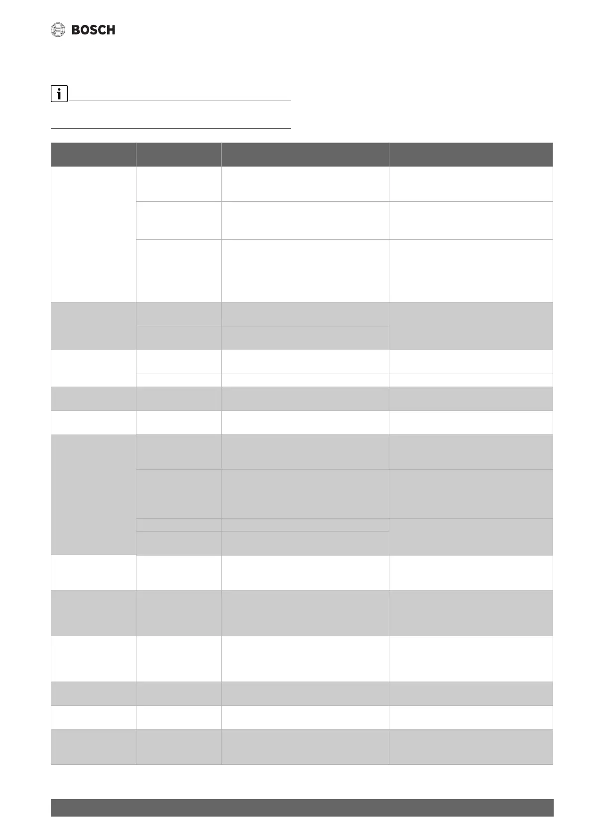
9.3 Boiler parameters
9.3.1 Basic boiler settings
Depending on which boiler type and burner type have been chosen,
special setting options will be displayed.
Submenu Settings/adjustment
range
Explanation Note
Boiler type None No boiler available. Control is used as standalone
master control unit with address 0 or as
substation.
Standalone as master control unit with address
0. Substation as control unit with address >0
SAFe The parameters of the SAFe are adopted by the
heat source. A boiler control is not installed in the
heat source.
Note selection at menu item Hydraulic.
( Chapter 5, page 8 and chapter 11.2,
page 32)
EMS The parameters of the boiler control the SAFe are
adopted by the heat source in the control unit.
Note selection at menu item Sensor.
Attention: the SI and external interlock terminal
must be opened!
( Chapter 5, page 8 and chapter 11.2,
page 32)
Hydraulic Boiler The heating circuit on the central module is used
as boiler circuit.
Boiler/heating circuit 00 with the terminals PK,
SR, FZ ( Chapter 9.4, page 21)
Heating circuit The heating circuit on the central module is used
as boiler circuit (00).
Sensor Heat source
(low loss header)
Heating circuit (Flow)
Boiler circulation pump No/Yes Setting that specifies whether a boiler circulation
pump is installed.
Chapter 11.1.1, page 32
Modulating pump No/Yes Setting that specifies the conditions according to
which the pump is controlled
Pump control mode In accordance with
boiler operating
conditions
The control operates within the limits specified
by the SAFe, e.g. maximum boiler temperature.
Off/On Setting that determines whether the modulating
pump is to be switched on and off via a 0....10 V
signal.
Digital activation of modulating pump.
Activation: On = 10 V, Off = 0 V
Prerequisite: continuous external power supply
to pump.
According to output ▶ Observe pump manufacturer's
specifications.
According to
temperature difference
Setting that specifies the conditions according to
which the pump is controlled
Temperature difference
between boiler and low
loss header
1...4...10 K Setting of the temperature differential between
temperature sensor in the system flow (FZ) and
boiler water temperature sensor.
Pump overrun time for
lead boiler
0...60...120 Min To utilise the heat stored in the heat source to the
maximum possible extent, a time must be
specified for which the pump should continue to
operate after the burner has been shut down.
Change the factory setting only in exceptional
cases.
Pump overrun time for
slave boiler
0...60...120 min To utilise the heat stored in the heat source to the
maximum possible extent, a time must be
specified for which the pump should continue to
operate after the burner has been shut down.
Change the factory setting only in exceptional
cases.
Voltage for min. flow
temp
0...10 V Specifies the voltage at which the minimum flow
rate occurs.
Observe pump manufacturer's specifications.
Voltage for max. flow
temp
0...10 V Specifies the voltage at which the maximum flow
rate occurs.
Observe pump manufacturer's specifications.
Boiler temperature
increase at low loss
header
No/Yes 5 K is added to the desired set value for the boiler
temperature, so that the set value can be reached
quickly and safely.