Installation
9
Control 8313 – 6720859567 (2017/03)
Note the following when making electrical connections:
• All electrical connections, safety measures and safety devices must
be implemented by an approved contractor, taking into account the
standards and guidelines that are applicable in each case as well as
the local regulations.
• Establish electrical connection as a fixed connection in accordance
with local/national regulations.
• Electrical connections are established as specified in the connection
diagram for the control unit and the module.
To prevent inductive influences:
▶ Make sure all low-voltage cables are routed separately to mains
voltage cables (min. clearance 100 mm).
• When installing the devices, ensure an earth connection is present.
• Do not exceed the total current stated on the data plate, and the
partial currents for each safety switch and connection.
• Before opening the control unit, disconnect all poles of the control
unit and secure against unintentional reconnection.
• Incorrect attempts to make connections under voltage may damage
the control unit beyond repair and lead to dangerous electric shocks.
▶ Establish electrical connections as specified in the connection
diagram of the control unit and the local conditions.
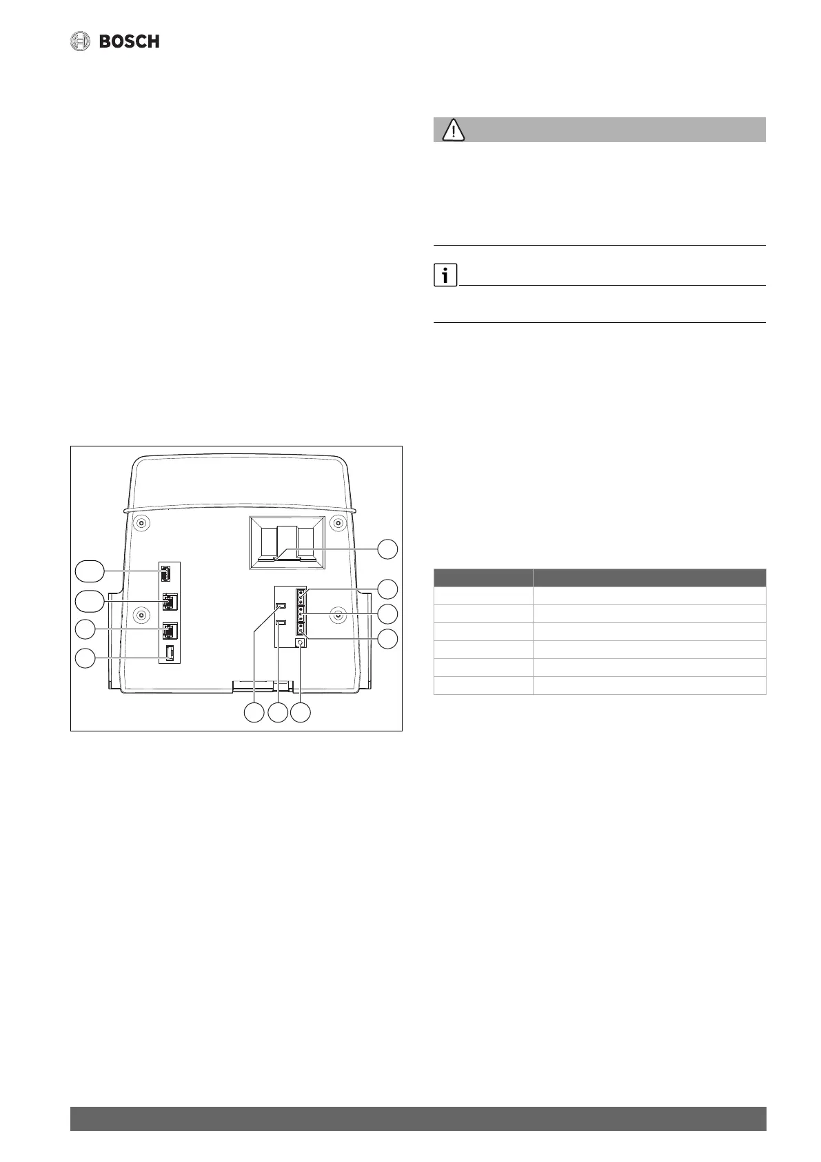
5.4 User interface connections (HMI)
Fig. 4 User interface connections
[1] Slide type insert for SD card
[2] CAN-BUS connection (no function, provided for
subsequent functions)
[3] Modbus-RTU connection for Bosch/Bosch CHP module
[4] EMS connection (connection for EMS heat source with its own
basic control (control panel))
[5] Address setting of control unit
[6] Jumper (J2) for activating the Modbus-RTU terminating resistance
[7] Jumper (J1) for activating the terminating resistance CAN-BUS
[8] Battery CR2032
[9] Network connection 2 (CBC-BUS)
[10] Network connection 1 (Internet, Modbus TCP/IP, CBC-BUS)
[11] USB connection
Depending on the use and configuration, the plug-in connections on the
rear of the user interface must be occupied.
Configuration of CAN-BUS/Modbus-RTU/EMS plug:
• Jumper for activating the Modbus-RTU terminating resistance
• Jumper for activating the CAN-BUS terminating resistance
5.5 Connecting the heat source to the control unit
5.5.1 Connection to the SAFe
WARNING:
Danger to life due to flue gas at the installation location!
With older SAFe software versions (not permitted here), the heat source
may start automatically in unfavourable circumstances!
Unfavourable scenario: connection between heat source (with old SAFe)
and ZM5313 is interrupted.
▶ Only use heat sources with SAFe with software version ≥ Table 3.
If a boiler with SAFe burner control unit is being connected, the EMS
connection has no function!
SAFe heat sources are heat sources that are equipped with a SAFe
(burner control unit) for burner control. The SAFe is directly connected
to the higher level plant control system (e.g. Control CC 8313).
As the software version of the connected heat source determines
whether or not the control functions correctly, the software version of
the SAFe must be checked directly following connection.
Connections:
• On the ZM5313 central module at the BUS SAFe and mains
SAFe terminals
• On the SAFe at the BUS and mains SAFe terminals.
Check SAFe version
▶ Check at the heat source whether the SAFe has at least one of the
software versions listed in table 3.
Table 3 SAFe version
0010005508-001
+-
3 2 13 2 1
2 1
J1
LAN1
USB1
LAN2
J2
567
2
1
3
4
9
8
10
11
SAFe Software version
10 V4.27
20 V4.23
30 V4.27
40 V4.23
42 V4.28
50 –
1)
1) No function with SAFe 50