Information on the boiler parameters main menu
Control 8313 – 6720859567 (2017/03)
32
11 Information on the boiler parameters main menu
11.1 General settings regarding boiler parameters
11.1.1 Setting up the pump function
The terminals of the PWM signal are not working.
Activation of the boiler circuit pump via 0...10 V
The boiler circulation pump can be connected in modulating operation
via a 0...10 V output (PK MOD).
▶ For the minimum and maximum voltage values of the pump, refer to
the specifications of the pump manufacturer.
▶ Setting the Voltage for min. flow temp and Voltage for max. flow
temp parameters.
0...10 V According to temperature difference
The pump modulation is activated so as to achieve the set temperature
differential between the system flow/differential sensor and boiler water
temperature sensor.
Recommendation with low loss header: set 0...10 V Output.
0...10 V according to output
The 0...10 V signal is subject to the currently required burner output:
• 100 % burner output = 10 V (maximum pump modulation)
• Minimum burner output = 0 V (minimum pump modulation)
Recommendation: install heat exchanger for system separation.
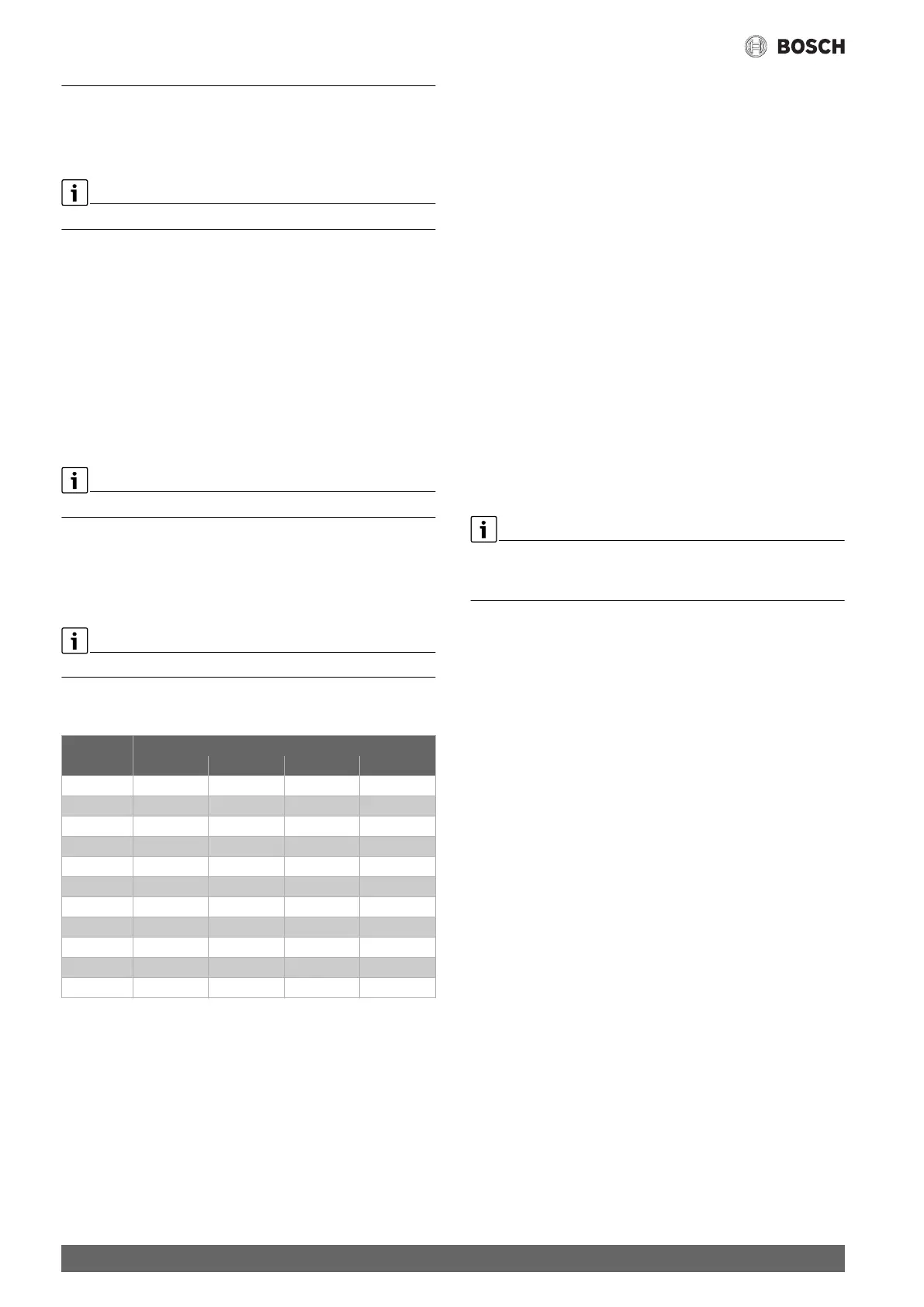
The boiler circuit pump must be sized to suit the heating system
hydraulics to ensure perfect operation:
Table 24 Recommended flow rates for sizing the boiler circuit pump PK
[m/h]
11.2 Maximum shutdown temperature
With EMS boilers, the maximum cut-off temperature is specified by the
SAFe of the heat source, which is connected to the control unit. The
maximum cut-off temperature can only be reduced in the control unit
menu.
The maximum cut-off temperature is set in the Boiler characteristics
menu under the menu item Maximum shutdown temperature.
If the heat source does not reach the maximum cut-off temperature that
has been entered, it may also be limited by external parameters. This
could be for example:
• a control unit in the boiler used
• a burner control unit (SAFe) in the heat source used
• a 0...10 V signal of an external setpoint value
11.3 Information on the FM-SI module
When several items of safety equipment connected to the safety module
are triggered, only one fault display appears. Only the input with the
lowest number appears as fault display. If additional safety equipment
has been triggered, these are displayed in the Monitor data menu.
Example
The safety equipment at FM-SI1 and FM-SI4 has been triggered. Only the
triggering of connection FM-SI1 appears in the display. Both of the
triggered connections can be seen in the Monitor data menu.
If a 230 V voltage is not supplied to the module because the plug-in
connector has not been inserted, it is not possible to evaluate the safety
inputs. A fault is displayed although the safety chain is closed.
Output
[kW]
Required temperature differential for heat source [K]
5 10 15 20
50 8.6 4.3 2.9 2.1
75 12.9 6.4 4.3 3.2
100 17.2 8.6 5.7 4.3
150 25.8 12.9 8.6 6.4
200 34.4 17.2 11.5 8.6
300 51.6 25.8 17.2 12.9
500 86.0 43.0 28.7 21.5
750 129.0 64.5 43.0 32.2
1000 172.0 86.0 57.3 43.0
1500 258.0 129.0 86.0 64.5
2000 343.9 172.0 114.6 86.0