Information on the Connectivity main menu
Control 8313 – 6720859567 (2017/03)
38
Lag boiler (Slave)
The control unit address of all lag boilers (Slaves) is greater than 0.
▶ Insert LAN cable in the LAN1 and LAN2 connection
( Fig. 13, [9], page 16).
▶ Set the address switch ( Fig. 13, [5], page 16) to 1.
To integrate further lag boilers:
▶ Establish connection following the same procedure described above.
▶ Set the address switch ( Fig. 13, [5], page 16) to 2 or higher.
An address must not appear twice.
▶ Observe chapter 8.2, page 16.
The LAN1 connection to the master control unit (address 0) is envisaged
for the Internet connection, or connection to a building services
management system via Modbus TCP/IP, and must be programmed
accordingly.
The LAN1 connection to control units with the address >0 can only be
used for internal communication between control units in the Control
8000 series. LAN1 can therefore not be programmed.
As a basic rule, the LAN2 connection can only be used for internal
communication between control units in the Control 8000 series. This
depends on the control unit address that has been set.
16.1.2 Control unit coupling
The Control unit coupling takes approx. 10 minutes. During this time,
the Master searches for nodes on the CBC bus. All registered control
units that are logged in appear in the overview of heat sources.
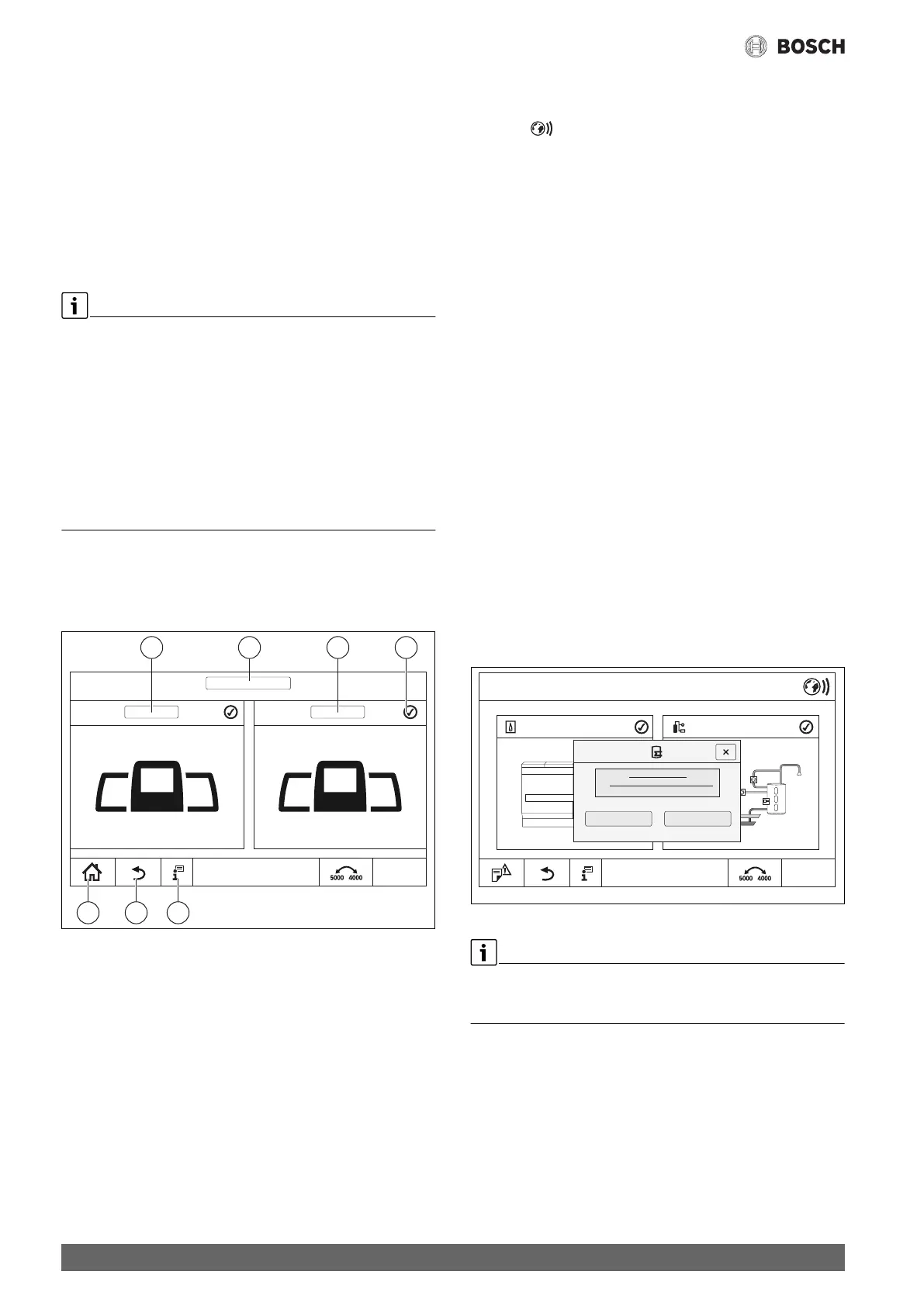
Fig. 23 Overview of heat sources
[1] Control unit (system) address 0
[2] Name of selected control unit
[3] Control unit (system) address 1
[4] Status display of control unit
[5] Further information on the selected control unit
[6] Press field to return to the previous level/screen of
the selected control unit
[7] Press field to access the selected control unit in the system
overview or in the control unit overview
Once started, the coupling process runs in the background.
To network the control units:
Slave
▶ Call up the service menu in every Slave ( Chapter 6.8, page 14).
▶ Tap the field.
▶ Activate network connection.
▶Start Control unit coupling.
▶ Couple additional Slaves as described above.
Once the coupling operation has been started for all Slaves:
▶ Confirm the Control unit coupling in the Master dialogue with
Continue.
The Slaves detected during the coupling process are registered as
nodes.
Once the coupling process is complete, a message appears to confirm
that the coupling was successful. If not all control units have been
detected, a fault is displayed:
▶ Check device connection and address allocation.
If a connection does not exist for a control unit that has been detected
once:
▶Start Control unit coupling in the master control unit.
The connection with the control unit is re-established.
16.2 Network connection
A connection with the MEC Remote Portal can be established via the
Internet using the control unit software. Individual parameters can be
called up and adjusted remotely via this link in the main menu.
It is not possible to access the service menu.
These parameters can only be adjusted locally (not via a telecontrol
system). If remote adjustment is activated, data can be specified or
modified remotely (e.g. via a telecontrol system).
The prompt asking whether you wish to allow adjustments to be made
remotely will be displayed as soon as the network connection has been
set up.
Fig. 24 Remote adjustment prompt
For security reasons, you must log in at the MEC Remote Portal in order
to establish the Internet connection. Every communication is sent or
received by the control unit via this portal.
0010010207-001
1 2 3
12:00
7 6 5
4
0010009550-001
12:00