Menu structure
Control 8313 – 6720859567 (2017/03)
20
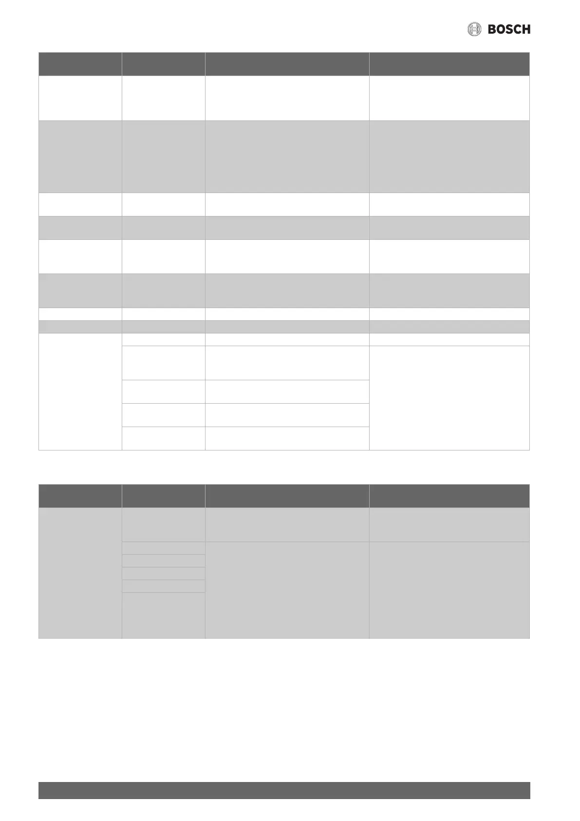
Table 8 Boiler characteristics menu
9.3.2 Settings of the safety equipment
Table 9 Safety equipment settings
External Heat Detection No/Yes Once sufficient heat to supply the system has
built up at sensor FZ, the heat source is
prevented from starting. If the system set value is
undercut by 4 K, the heat source is started.
The temperature sensor FZ is in the low loss
header or buffer cylinder.
Maximum shutdown
temperature
30...85...99 °C The burner is switched off once the heating flow
temperature reaches the maximum cut-off
temperature at the latest.
The maximum possible cut-off temperature is
specified by the SAFe of the connected heat
source.
Change the factory setting only in exceptional
cases. The value can only be reduced.
Chapter 11.2, page 32
Maximum boiler output 0...100 % Limiting the performance of the heat source This function is active in heating and DHW
mode.
Cycle deactivation 0...10...60 min Setting the blocking time between switching off
the heat source and switching it back on
This function is active in heating and DHW
mode.
Negative hysteresis -30...-4...0 K Setting that specifies when the set value is
undercut what the difference in temperature
should be before heat production starts
Positive hysteresis 0...2...15 K Setting that specifies when the set value is
exceeded what the difference in temperature
should be before heat production ends
Max. Air Correction -9...0...9 Matching the fan speed The function depends on the heat source.
Min. Air Correction -9...0...9 Matching the fan speed The function depends on the heat source.
Service display None
After hours Maintenance according to hours run
(only in control units with direct activation of
heat source)
• The service display is recorded in the fault
history can be displayed via the building
services management system.
• The status of the service display can be
requested in the fault history.
• The service display can be reset in the Reset
menu.
Next maintenance Setting the number of hours until maintenance is
next due
Burner run time since
last maintenance
Number of hours that have elapsed since
maintenance was last carried out.
Date Service display set according to date: entry of
next maintenance deadline
Submenu Settings/adjustment
range
Explanation Note
FM-SI1...FM-SI5 Free/Allocated Inputs for fault displays Only if a FM-SI is installed. Inputs must be
activated ( Chapter 6.7, page 13 and
chapter 11.3, page 32).
Max. pressure 1 Selection of a name for the connected safety
equipment or entry of an individual name
Max-pressure1/2 = maximum pressure
limiter 1 or 2
Min-pr.WMS = minimum pressure limiter
or low water indicator
STB2 Safety = 2nd safety temperature limiter
This must be connected to input SI1 when using
a condensate neutraliser.
Unallocated inputs of the safety chain module
must be jumpered.
Max. pressure 2
Min-PressWMS
Neutralisation
STB 2 safe.
Submenu Settings/adjustment
range
Explanation Note