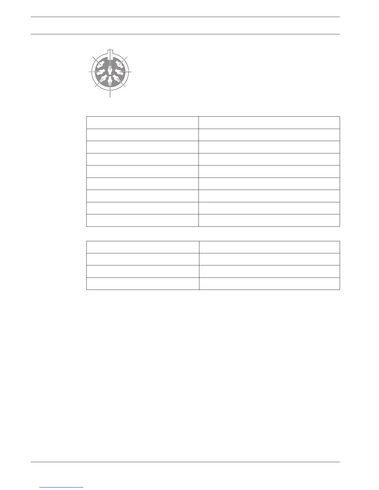
Figure 6.31: Audio input, connection
Pin Signal
1 Signal in, +
2 Microphone, common
3 Signal in, -
4 Microphone LED (max. 2 mA)
5 Request-to-speak LED (max. 7 mA)
6 Microphone button
7 +12 V(DC) (max. 20 mA)
8 LED ring control
Table 6.19: Audio input, connection
Pin
Component
4 (-) to 7 (+) Microphone on LED
5 (-) to 7 (+) Request-to-speak LED
6 to 7 Momentarily microphone switch
Table 6.20: Connections
Typically, you will connect DCN-FMIC Microphone Connection Panels (refer to DCN-FMIC
Microphone Connection Panel, page 40) to the audio inputs.
For information about configuration of the DCN-DDI Dual Delegate Interface refer to DCN-DDI
Dual Delegate Interface, page 213.
134
en | Connection Conference System
2013.11 | V2.0 | DCN-NG_OM_V4.x Operation Manual Bosch Security Systems B.V.
 Loading...