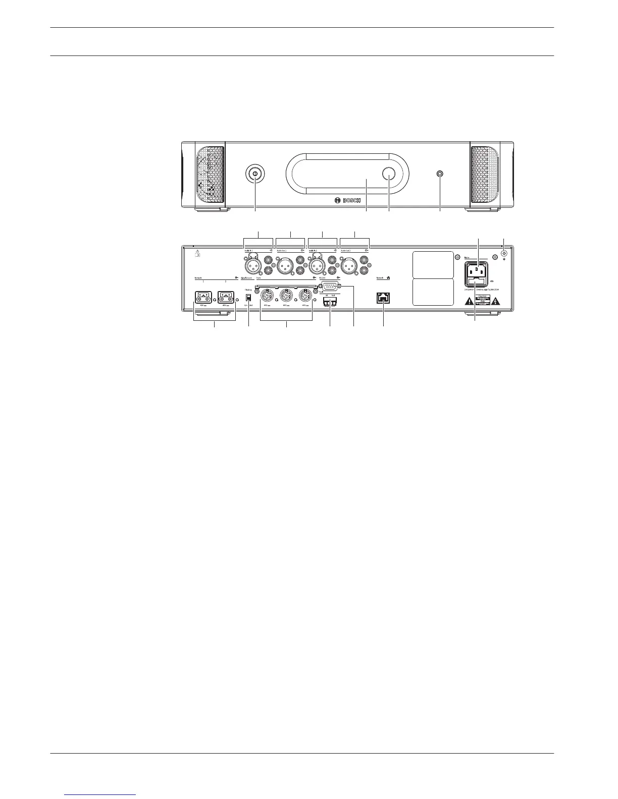
Figure 3.2: Front and rear view of CCU2
1. On/off switch - Power on or off the central control unit.
2. Display - Shows the configuration menu.
3. Knob - Operates the configuration menu and the volume level of the system.
4. Headphones socket - Headphone connection.
5. Audio inputs - Connect the central control unit to external analog audio sources. The
functions of the audio inputs are:
Audio input 1: Floor
Audio input 2: Selectable recorder/delegate loudspeaker/ mix-minus/insertion.
Interpreter floor insertion/local floor.
6. Audio outputs - Connect the central control unit to external analog audio devices. The
functions of the audio outputs are:
Audio output 1: PA
Audio output 2: Selectable recorder/delegate loudspeaker/ mix-minus/insertion.
Interpreter floor insertion/local floor.
7. Power inlet - Connects the central control unit to the mains power supply with a power
cable.
8. Ground screw - Connects the central control unit to ground.
9. Fuse holder - Prevents damage to the internal power supply unit of the central control
unit.
10. Ethernet socket - Connects the central control unit (DCN-CCU2) to the PC, remote
controller or in a multi CCU system to the master central control unit.
11. RS232 - Connects video cameras to the central control unit.
12. Fault contact - Connects the central control unit to devices to sense the condition of the
central control unit.
13. DCN sockets with cable locking facility - Connects the central control unit to the DCN.
14. Ground lift - Default: grounded. Do not ground more than one mains powered device to
prevent humming sound caused by ground loops.
3.1
14 en | System Overview Conference System
2013.11 | V2.0 | DCN-NG_OM_V4.x Operation Manual Bosch Security Systems B.V.